Speed control device for vehicle

a technology for controlling devices and vehicles, applied in vehicle position/course/altitude control, process and machine control, instruments, etc., can solve problems such as speed not being controlled smoothly, and achieve the effect of suppressing the vehicle and reducing discomfor

Inactive Publication Date: 2012-09-11
AISIN AW CO LTD
View PDF16 Cites 7 Cited by
  • Summary
  • Abstract
  • Description
  • Claims
  • Application Information

AI Technical Summary

Benefits of technology

[0005]It is an object of the present invention to provide a speed control device for a vehicle that is capable of achieving smooth speed control when the vehicle passes through a curve.
[0014]With the structure described above, the first and the second (and the third) reference points used for calculating the target vehicle speed are set based on the curve shape (more specifically, on the change in radius of curvature of the curve), and the reference point used for calculating the current target vehicle speed is shifted sequentially as the position of the vehicle moves ahead. As a result, smooth speed control can be achieved while the vehicle is running along the curve.
[0015]In other words, the single deceleration reference point (first reference point) and the single maintenance reference point (second reference point) (and the single acceleration reference point (third reference point)) are set (independently of nodes stored in memory in advance) within the single curve, and the speed control is performed while the vehicle is running along the curve. In this process, the operations of the “determination on possibility of passing” and the “setting of target vehicle speed” are not performed for each node, as is performed in the device described in the Japanese Patent Application Publication No. JP-A-7-125565 mentioned above. Consequently, the vehicle can pass through the single curve smoothly.
[0018]With the structure described above, when the driver performs an accelerating operation while the vehicle is running along the curve, the target vehicle speed (accordingly, an actual vehicle speed) can be made higher than that when the driver performs no accelerating operation. That is, the accelerating operation by the driver can be reflected in the speed control. Consequently, the speed control can be achieved in response to the intention of the driver to accelerate the vehicle, giving little sense of discomfort to the driver.
[0019]When the accelerating operation by the driver is reflected in the speed control in this manner, it is preferable that the target vehicle speed determination unit be structured so as to determine the target vehicle speed so that an increment from the target vehicle speed when the operating amount is zero does not exceed a predetermined upper limit. By being structured in this manner, it is possible to suppress the vehicle from being unnecessarily accelerated when the vehicle runs along the curve, thus enabling the vehicle to pass through the curve in a stable manner.

Problems solved by technology

As a result, the speed may not be controlled smoothly when the vehicle runs along a curve (the speed of the vehicle does not change smoothly).

Method used


Image

  • Speed control device for vehicle
  • Speed control device for vehicle
  • Speed control device for vehicle

Examples


Embodiment Construction

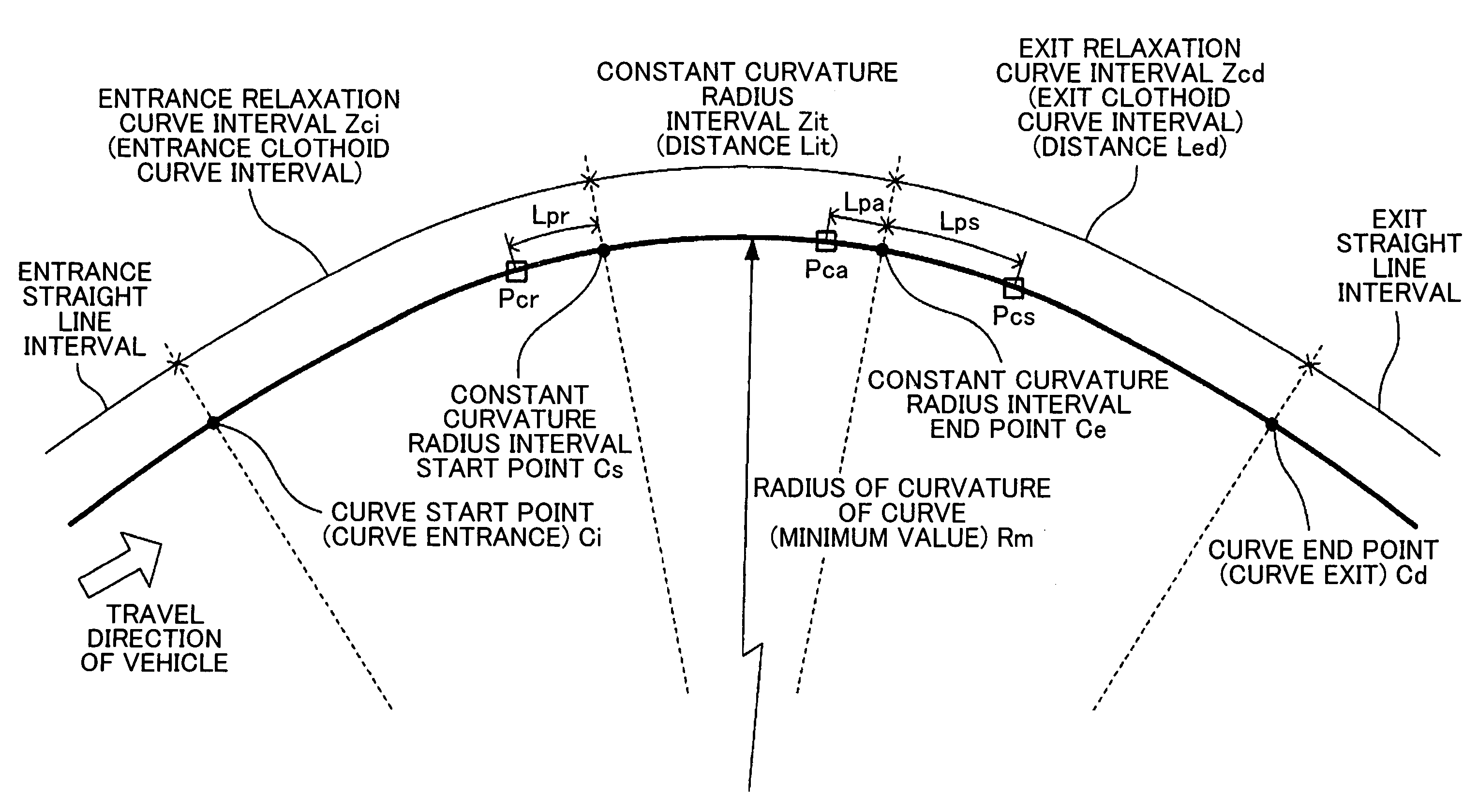
[0030]An embodiment of a speed control device for a vehicle according to the present invention will be described below with reference to the accompanying drawings.

[0031](Structure)

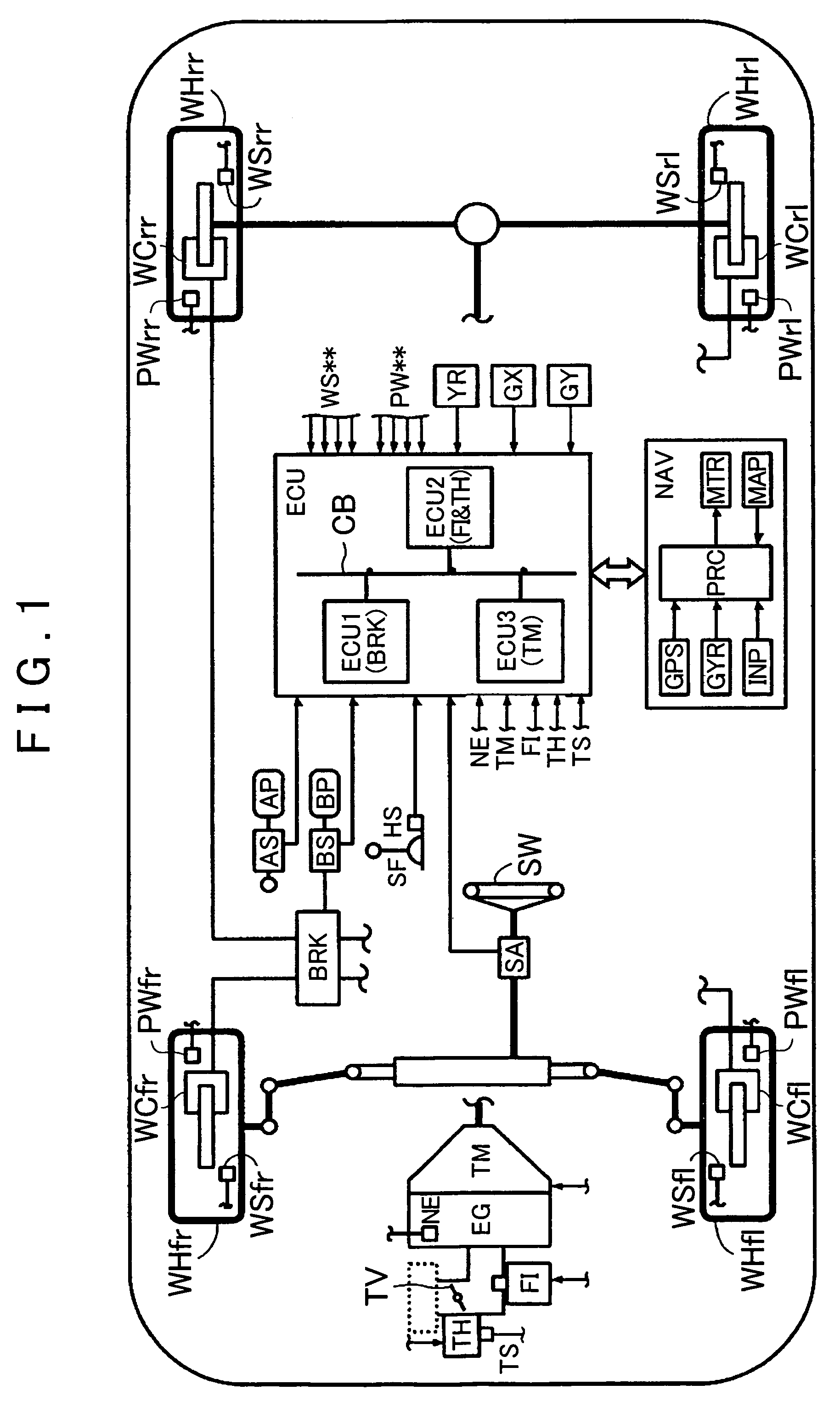
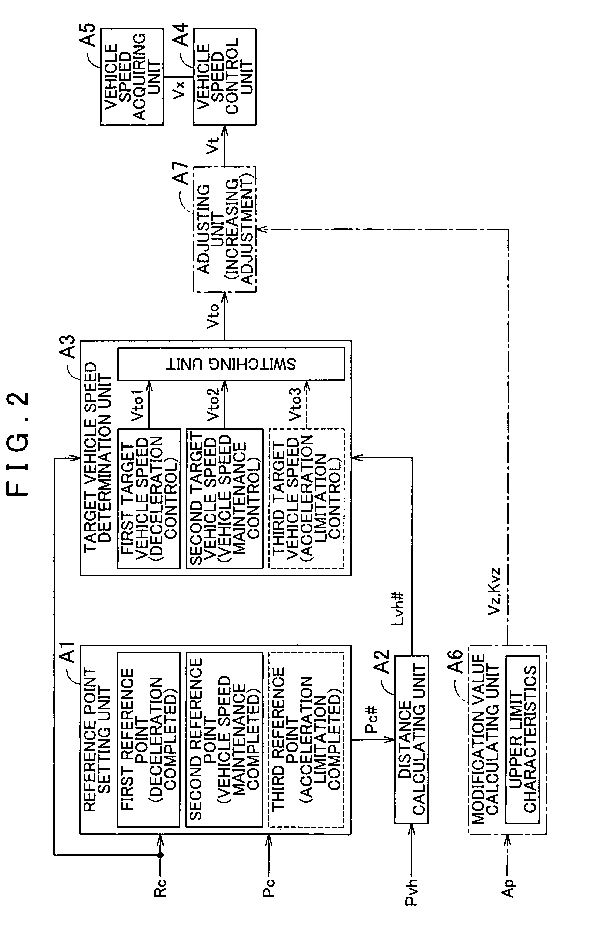
[0032]FIG. 1 shows a schematic structure of a vehicle equipped with a speed control device (hereinafter referred to as “present device”) according to an embodiment of the present invention. The present is equipped with an engine EG serving as a power source of the vehicle, an automatic transmission TM, a brake actuator BRK, an electronic control unit ECU, and a navigation device NAV.

[0033]The engine EG is, for example, an internal combustion engine. That is, an opening of a throttle valve TV is regulated by a throttle actuator TH in response to operation of an accelerator pedal (acceleration operating member) AP by a driver. A fuel injection actuator (injector) FI injects fuel of a quantity proportional to the quantity of intake air regulated depending on the opening of the throttle valve TV. As a result, ...


PUM


Abstract

A speed control device includes: a reference point setting unit that sets, based on shape and position of a curve in advance of a vehicle, first and second reference points within the curve, the second reference point being nearer the curve exit than the first reference point; a distance calculating unit that calculates, based on the vehicle location and the reference points, first and second distances, between the vehicle and the first and second reference points, respectively; a target speed determination unit that determines, based on the curve shape and the first and second distances, the first and second target vehicle speeds to be maintained, respectively, before and after passing the first reference point; and a speed control unit that controls the speed of the vehicle based on the target speeds and the detected speed of the vehicle.

Description

INCORPORATION BY REFERENCE[0001]The disclosure of Japanese Patent Application No. 2008-249580 filed on Sep. 29, 2008, including the specification, drawings and abstract is incorporated herein by reference in its entirety.BACKGROUND OF THE INVENTION[0002]The present invention relates to a speed control device for a vehicle, and more particularly to a speed control device for a vehicle that controls a speed at which the vehicle runs along a curve.DESCRIPTION OF THE RELATED ART[0003]Various types of speed control devices are known as those performing such speed control as described above. Japanese Patent Application Publication No. JP-A-7-125565 describes an automatic cruise controller that “calculates, based on an host vehicle position P0 and a look-ahead distance L, a node N0 included in the range within the look-ahead distance L on a first curve as an assumed host vehicle position P1, and using the assumed host vehicle position P1 as a reference point, determines the possibility of ...

Claims


Application Information

Patent Timeline
Patent Type & Authority Patents(United States)
IPC IPC(8): G05D1/00B60T7/12B60W10/04B60W10/06B60W10/10B60W10/18B60W10/188B60W30/00B60W30/02B60W30/14
CPCB60K31/0066B60W30/16B60W40/072B60W40/076B60W2550/143B60W2720/10B60W30/18145B60W2552/20B60W2552/30
Inventor MIYAJIMA, TAKAYUKIYASUI, YOSHIYUKIKOTO, HIDEAKIKODAMA, HIROYUKIMARUYAMA, MASAKI
Owner AISIN AW CO LTD
Why Eureka
Try Eureka