Fitting

a technology of fittings and walls, applied in the field of fittings, can solve the problems of difficult manufacturing of variations in thickness in composite materials, particularly laminates, and difficulty in forming fittings of the required strength without having to increase the thickness of the walls of the fitting to unacceptable levels, so as to reduce weight and reduce weight

Active Publication Date: 2012-09-18
AIRBUS OPERATIONS LTD
View PDF14 Cites 17 Cited by
  • Summary
  • Abstract
  • Description
  • Claims
  • Application Information

AI Technical Summary

Benefits of technology

[0010]The reinforcement element provides an alternative means of strengthening the end wall of the fitting, without requiring any variation in the thickness of the composite part. This makes an optimum configuration much easier to achieve. The reinforcement element also engages at least the first and second corners to provide further reinforcement and to counteract the tendency of the layers to come apart at the corners of the composite part.
[0013]The edge of the upper wall opposite to the end wall may be formed with a recess to reduce weight and / or permit easy access to the reinforcement element.
[0014]Typically at least one of the side walls of the composite part has an edge which is inclined at an acute angle to the base to reduce weight and / or permit easy access to the reinforcement element.

Problems solved by technology

However the different properties of composite materials (in comparison with metals) makes it difficult to form a fitting of the required strength without having to increase the thickness of the walls of the fitting to unacceptable levels.
This variation in thickness is difficult to manufacture in a composite material, particularly a laminate.

Method used


Image

  • Fitting
  • Fitting
  • Fitting

Examples


Embodiment Construction

)

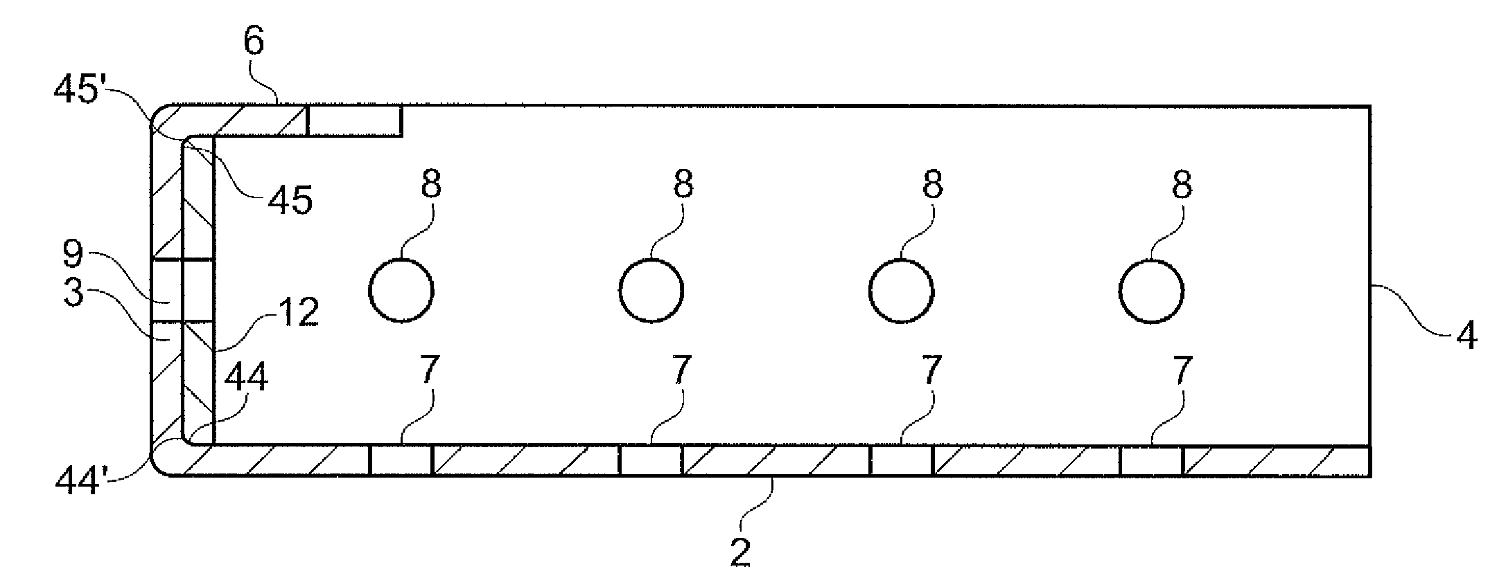
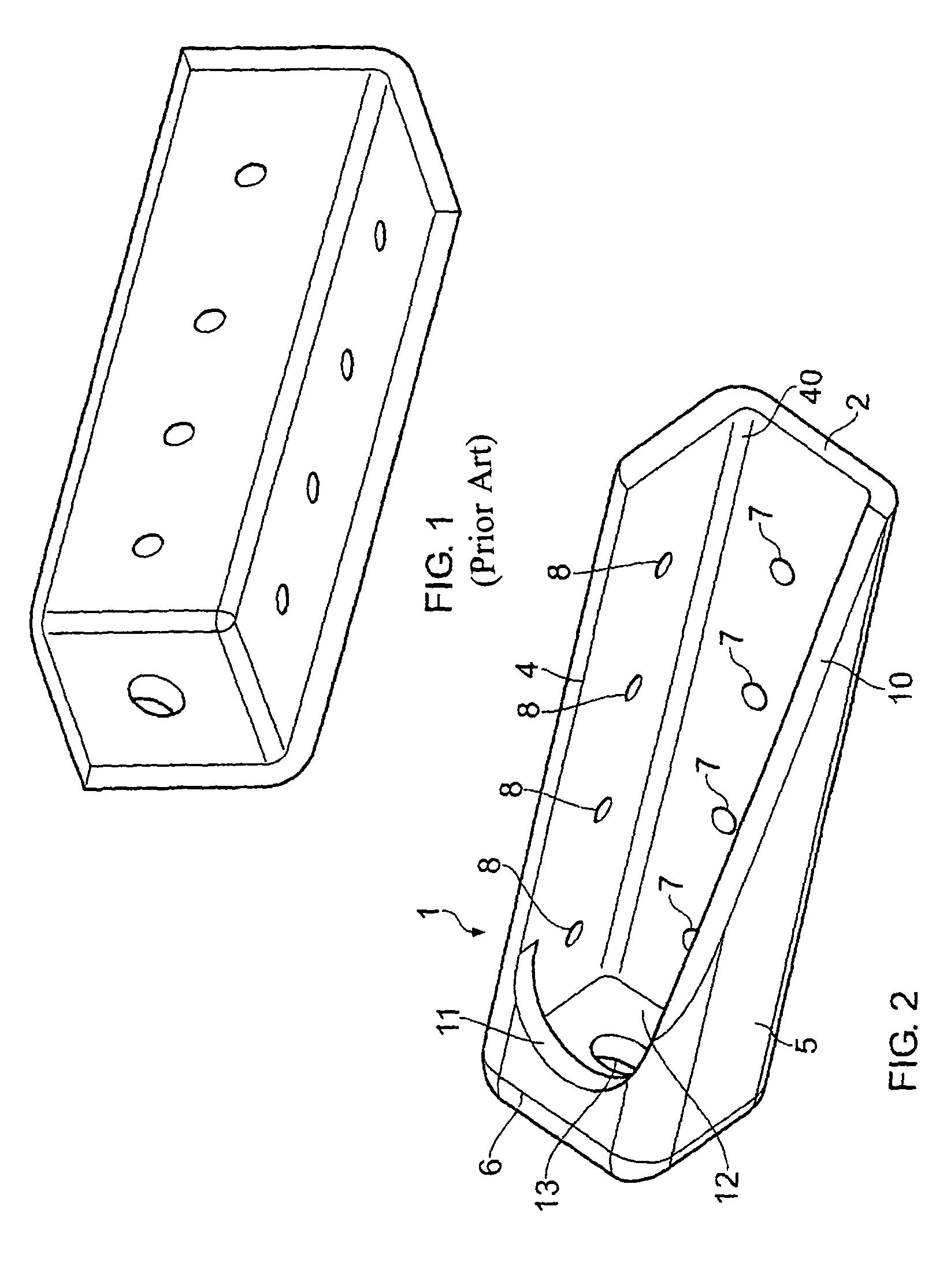
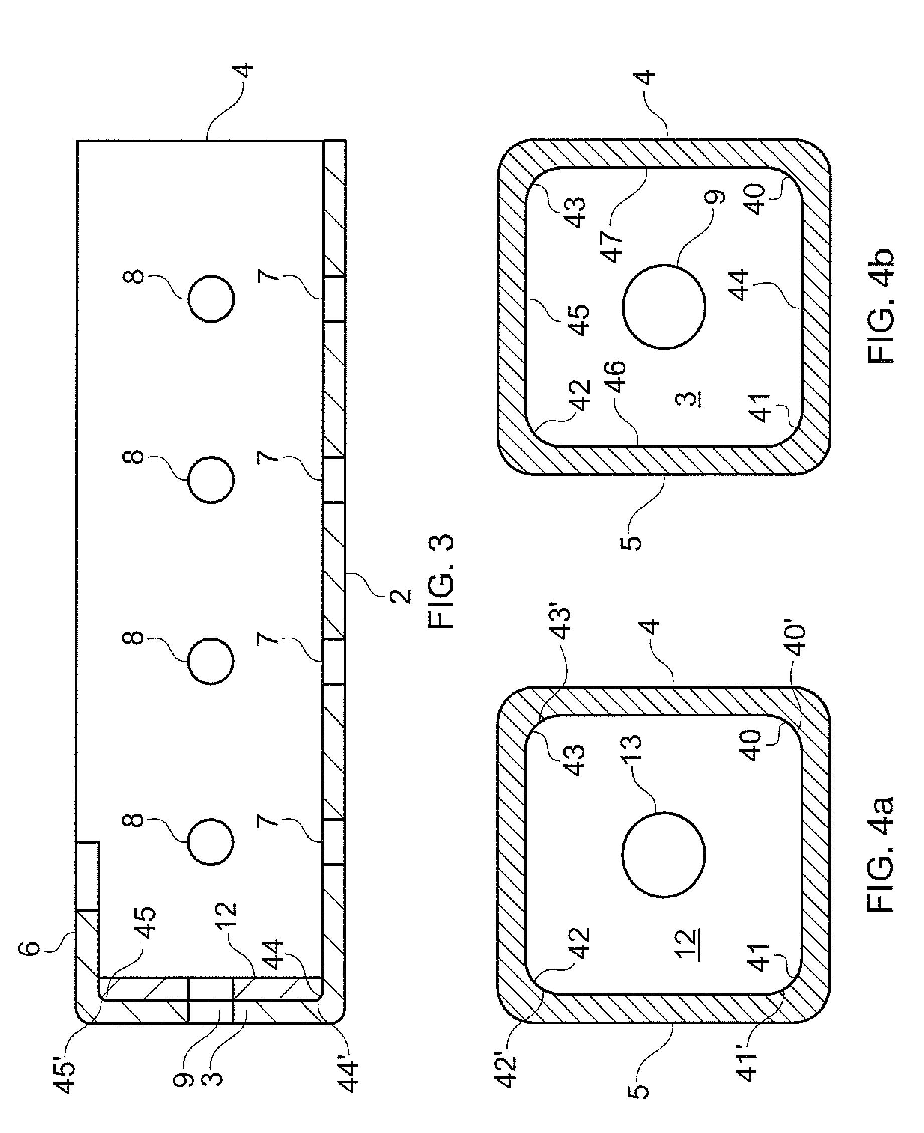
[0037]Referring to FIGS. 2-4b, a corner fitting 1 comprises a composite part having a base 2, an end wall 3, a left side wall 4, a right side wall 5, and an upper wall 6 which meet at eight corners 40-47.

[0038]The composite part of the fitting 1 is manufactured from a composite material using either pre-impregnated tapes or fabrics, woven textiles or non-crimp fabrics, 3D woven preforms, short or long fibre moulding techniques, or dry fibre placement. The reinforcement fibres may be for example carbon fibre, and the matrix of the composite may be either thermosetting or thermoplastic.

[0039]In the case of a 3D woven preform, the preform (woven into the desired shape) is placed in a moulding cavity, and compressed by a set of mandrels to mould the part into its final shape. After the moulding step, the preform is also infused with matrix material. In the case of a thermosetting matrix, the matrix is cured by heating above its curing temperature during moulding.

[0040]In the case of 2D...


PUM


Abstract

A fitting for joining a first component to a second component, the fitting comprising a composite part and a reinforcement element. The composite part is formed from a composite material and comprises: a base; an end wall meeting the base at a first corner; and a side wall meeting the end wall at a second corner and the base at a third corner. The reinforcement element is shaped such that it can be fitted to the composite part and engage the end wall of the composite part, the first corner of the composite part; and the second corner of the composite part.

Description

[0001]This application is the U.S. national phase of International Application No. PCT / GB2007 / 050554, filed 18 Sep. 2007, which designated the U.S. and claims priority to Great Britain Application No. 0619512.7, filed 3 Oct. 2006, the entire contents of each of which are hereby incorporated by reference.FIELD OF THE INVENTION[0002]The present invention relates to a fitting for joining a first component such as a centre wing box to a second component such as a lateral wing box.BACKGROUND OF THE INVENTION[0003]A conventional tension corner fitting for joining a lateral wing box to a centre wing box is shown in FIG. 1. The fitting comprises a base; an end wall meeting the base at a first corner; and a side wall meeting the base at a second corner and the end wall at a third corner. The base and side wall are bolted to one of the wing boxes, and the end wall is bolted to the other.[0004]Such fittings are conventionally formed from a metallic material. It would be desirable to form a fit...

Claims


Application Information

Patent Timeline
Patent Type & Authority Patents(United States)
IPC IPC(8): B64C1/06
CPCB64C1/26
Inventor KALLINEN, RISTOPAYNE, CHRISTOPHER
Owner AIRBUS OPERATIONS LTD
Why Eureka
Try Eureka