Tool for implanting expandable intervertebral implant

a technology of intervertebral implants and tools, which is applied in the field of tools for implanting expandable intervertebral implants, can solve the problems of disc space, so drastic decrease in spacing, and myriad of problems for patients

Active Publication Date: 2012-09-18
STRYKER EURO OPERATIONS HLDG LLC
View PDF218 Cites 280 Cited by
  • Summary
  • Abstract
  • Description
  • Claims
  • Application Information

AI Technical Summary

Benefits of technology

[0006]A second aspect the present invention may be another expandable implant for implantation between two vertebral bodies. In one embodiment according to this second aspect, the implant may include a first member, the first member including a first vertebral contact surface and a first interior surface, a second member, the second member including a second vertebral contact surface and a second interior surface, the first and second interior surfaces facing towards one another, a strut attached to both the first and second members, and first and second wedges disposed between the first and second interior surfaces, one of the first or second wedges including a bulleted or rounded surface for aiding in insertion of the expandable implant between the two vertebral bodies. Preferably, in this embodiment, movement of the first wedge towards the second wedge causes an increase in a distance between the first and second interior surfaces.
[0007]In other embodiments of the second aspect, each of the first and second wedges is attached to each of the first and second members by deformable tethers. The first wedge may include first and second angled wedge surfaces for cooperating with first and second angled interior surfaces of the first and second members respectively, the second wedge may include third and fourth angled wedge surfaces for cooperating with third and fourth angled interior surfaces of the first and second members respectively, and movement of the first and second wedges towards one another may be permitted, while movement of the first and second wedges away from one another is prevented. This may be the case because the first, second, third, and fourth wedge surfaces and the first, second, third, and fourth interior surfaces each include teeth. Furthermore, the first and second members and the first and second wedges may cooperate to define at least one aperture through the implant adapted for bone growth therethrough.
[0008]A third aspect of the present invention may be another expandable implant for implantation between two vertebral bodies. According to one embodiment of this third aspect, the implant may include a first member, the first member including a first vertebral contact surface and a first interior surface, a second member, the second member including a second vertebral contact surface and a second interior surface, the first and second interior surfaces facing towards one another, a strut attached to both the first and second members, and first and second wedges disposed between the first and second interior surfaces. Preferably, in this embodiment, movement of the first wedge towards the second wedge causes an increase in a distance between the first and second interior surfaces, and at least one of the first and second wedges is prevented from torsionally moving with respect to the first and second members.
[0010]A fourth aspect of the present invention is another expandable implant for implantation between two vertebral bodies. One embodiment of this fourth aspect includes a first member, the first member including a first vertebral contact surface and a first interior surface having a first and third angled interior surfaces, a second member, the second member including a second vertebral contact surface and a second interior surface having second and fourth angled interior surfaces, the first and second interior surfaces facing towards one another, a strut attached to both the first and second members, a first wedge disposed between the first and second interior surfaces, the first wedge including first and second angled wedge surfaces for cooperating with the first and second angled interior surfaces of the first and second members respectively, and a second wedge disposed between the first and second interior surfaces, the second wedge including third and fourth angled wedge surfaces for cooperating with the third and fourth angled interior surface of the first and second members respectively. Preferably, in this embodiment, movement of the first wedge towards the second wedge causes an increase in a distance between the first and second interior surfaces, and movement of the first and second wedges towards one another may be permitted, while movement of the first and second wedges away from one another is prevented.
[0012]A fifth aspect of the present invention is yet another expandable implant for implantation between two vertebral bodies. In one embodiment of this fifth aspect, the implant includes a first member, the first member including a first vertebral contact surface and a first interior surface having a first and third angled interior surfaces, a second member, the second member including a second vertebral contact surface and a second interior surface having second and fourth angled interior surfaces, the first and second interior surfaces facing towards one another, a plurality of struts attached to both the first and second members, a first wedge disposed between the first and second interior surfaces, the first wedge including first and second angled wedge surfaces for cooperating with the first and second angled interior surfaces of the first and second members respectively, a first tether connecting the first wedge to one of the first or second members, a second wedge disposed between the first and second interior surfaces, the second wedge including third and fourth angled wedge surfaces for cooperating with the third and fourth angled interior surface of the first and second members respectively, and a first tether connecting the first wedge to one of the first or second members. Preferably, in this embodiment, movement of the first wedge towards the second wedge causes an increase in a distance between the first and second interior surfaces, and the first, second, third, and fourth wedge surfaces and the first, second, third, and fourth interior surfaces each include teeth. In another embodiment, one of the first or second wedges may include a bulleted or rounded surface for aiding in insertion of the expandable implant between the two vertebral bodies.
[0014]In other embodiments of the sixth aspect, the moving step may be performed through the use of a deployment tool. The inserting step may also be performed through the use of the deployment tool. In certain embodiments, the implant may further include at least one deformable strut and more than one wedge. Each wedge may be attached to at least one of the first or second members by a deformable tether, or in some cases, the wedges may be attached to both members by deformable tethers. Additionally, the implant may further include structure which allows for the movement of the at least one wedge in a first direction, but prevents movement of the wedge in an opposition direction. Furthermore, the wedge may be prevented from torsionally rotating with respect to the first and second members.

Problems solved by technology

Whether due to the degeneration of the intervertebral disc over time or because of an injury, a decrease in spacing between vertebral bodies can cause a myriad of problems for a patient, the least of which is pain resulting from the pinching of nerves between the bodies.
Nonetheless, there exist certain extreme cases of degradation of the disc space which require extreme measures in order to restore the natural spacing.
Often, the decrease in spacing will be so drastic that some amount of distraction of the adjacent vertebral bodies will be required.

Method used


Image

  • Tool for implanting expandable intervertebral implant
  • Tool for implanting expandable intervertebral implant
  • Tool for implanting expandable intervertebral implant

Examples


first embodiment

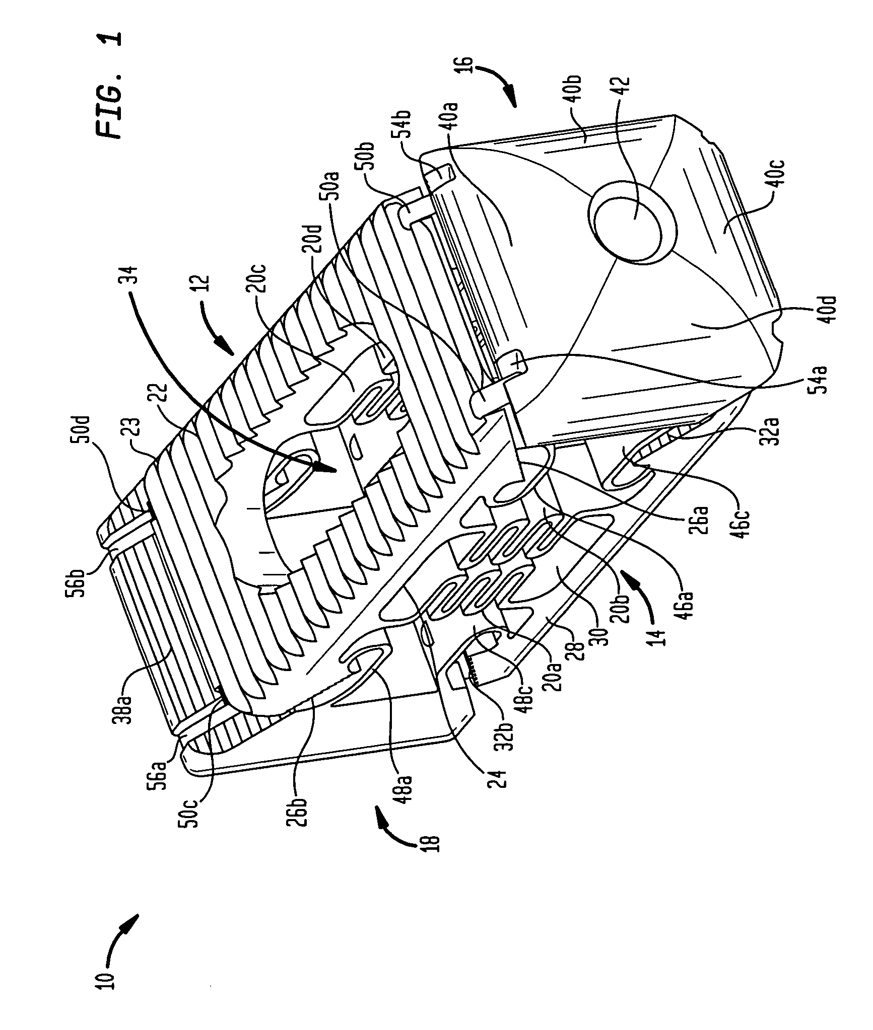
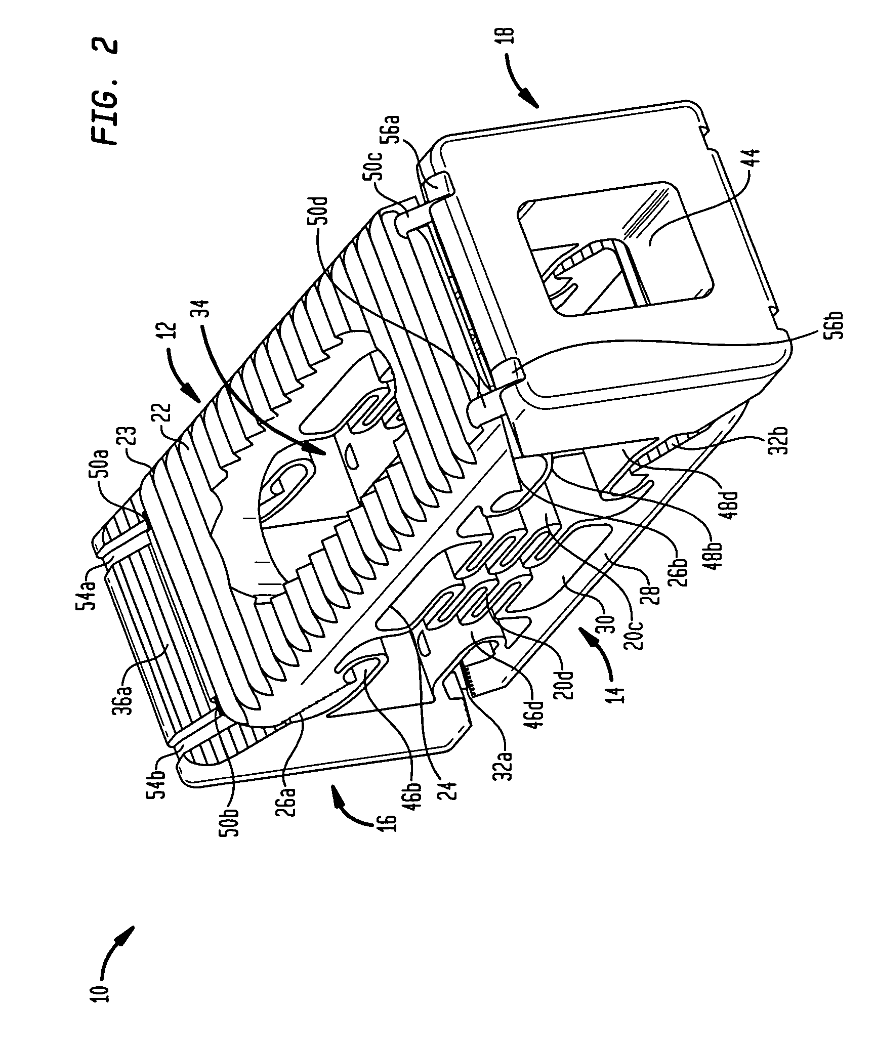
[0036]Referring to the drawings, wherein like reference numerals refer to like elements, FIGS. 1-6 depict a first embodiment expandable intervertebral implant, designated generally by reference numeral 10. As is shown in the drawings, implant 10 includes, among other elements that will be discussed below, a first member 12, a second member 14, a first wedge 16, a second wedge 18, and a plurality of struts 20a-d. Implant 10 is designed so that is capable of expanding from a generally unexpanded state (shown in FIGS. 1-5) to a fully expanded state (shown in FIG. 6), as well as several different partial expended states therebetween. The specific details of the structure and the operation of implant 10 will be discussed further below.

[0037]As is shown in FIGS. 1-6, first and second members 12 and 14 are generally planar plate-like elements capable of contacting and supporting a portion of vertebral bodies implant 10 is inserted between. First member 12 includes a first vertebral body co...

second embodiment

[0053]FIGS. 7-9 depict a second embodiment implant 110. Essentially, implant 110 is substantially similar to implant 10 save for the inclusion of different torsion inhibiting elements. Because of the similarity of implant 110 with implant 10, similar or identical elements will be referred to with like reference numerals within the 100-series of numbers. For example, implant 110 includes first and second members 112 and 114 which are expandable upon movement of first and second wedges 114 and 116 towards one another. However, in the embodiment shown in FIGS. 7-9, first and second members 112 and 114 are provided with apertures (150a-d and 152a-d, respectively) which are capable of receiving protuberances (not shown). For example, these apertures may receive pins, screws, or plugs which extend somewhat below the angled interior surfaces of first and second members 112 and 114, respectively. First and second wedges 116 and 118, on the other hand, each include four channels for cooperat...


PUM


Abstract

An expandable intervertebral implant and tool for use in implanting same are disclosed. The tool is useful in retaining the implant in a non-expanded state throughout insert of the implant between adjacent vertebral bodies. Among other elements, the tool includes a rod, a sleeve placed over the rod, and a locking knob attached to the rod and the sleeve to fix them with respect to each other. This construct preferably aids in preventing movement of the various components of the implant, including first and second members and first and second wedges. A method of attaching inserting the implant through the use of the tool and attaching the tool to the implant are also disclosed.

Description

BACKGROUND OF THE INVENTION[0001]Surgeons are performing more and more spinal surgeries to correct different spinal defects in the hopes of reducing pain and restoring normal or close to normal movement. One area of particular interest lies in the restoration of normal spacing between adjacent vertebral bodies. Whether due to the degeneration of the intervertebral disc over time or because of an injury, a decrease in spacing between vertebral bodies can cause a myriad of problems for a patient, the least of which is pain resulting from the pinching of nerves between the bodies. Correcting this problem is often very important to returning a patient to his or her normal level of activity and / or managing the pain associated with a degenerative spinal problem.[0002]Over the years, there have been many different techniques employed in restoring the normal disc space. For instance, solid fusion devices have been implanted in many patients in the hopes of both restoring normal disc spacing...

Claims


Application Information

Patent Timeline
Patent Type & Authority Patents(United States)
IPC IPC(8): A61B17/60A61F2/44
CPCA61F2/447A61F2/4611A61F2002/30112A61F2002/30383A61F2002/30461A61F2002/3052A61F2002/30556A61F2002/30565A61F2002/30579A61F2002/30772A61F2002/30904A61F2002/4627A61F2002/4629A61F2220/0025A61F2220/0075A61F2230/0004A61F2250/0009
Inventor CIPOLETTI, ROBERTALHEIDT, THOMAS
Owner STRYKER EURO OPERATIONS HLDG LLC
Why Eureka
Try Eureka