Electrical energy generator and method

a technology of electric energy generator and generator, which is applied in the direction of machines/engines, mechanical equipment, and magnetic circuit shapes/forms/construction, etc., can solve the problem of not disclosing a new electrical energy generator, and achieve the effect of reducing the load of the rotor member, minimizing the generation of heat, and effectively generating maximum energy outpu

Inactive Publication Date: 2012-09-18
SOMERVILLE CRIS D
View PDF2 Cites 17 Cited by
  • Summary
  • Abstract
  • Description
  • Claims
  • Application Information

AI Technical Summary

Benefits of technology

[0011]Still yet another object of the present invention is to provide a new electrical energy generator that senses wind speed and accordingly adjusts the positioning of the coils relative to the magnets to reduce the load of the rotor member thus allowing

Problems solved by technology

While these devices fulfill their respective, particular objectives and requirements, the afor

Method used


Image

  • Electrical energy generator and method
  • Electrical energy generator and method
  • Electrical energy generator and method

Examples


Embodiment Construction

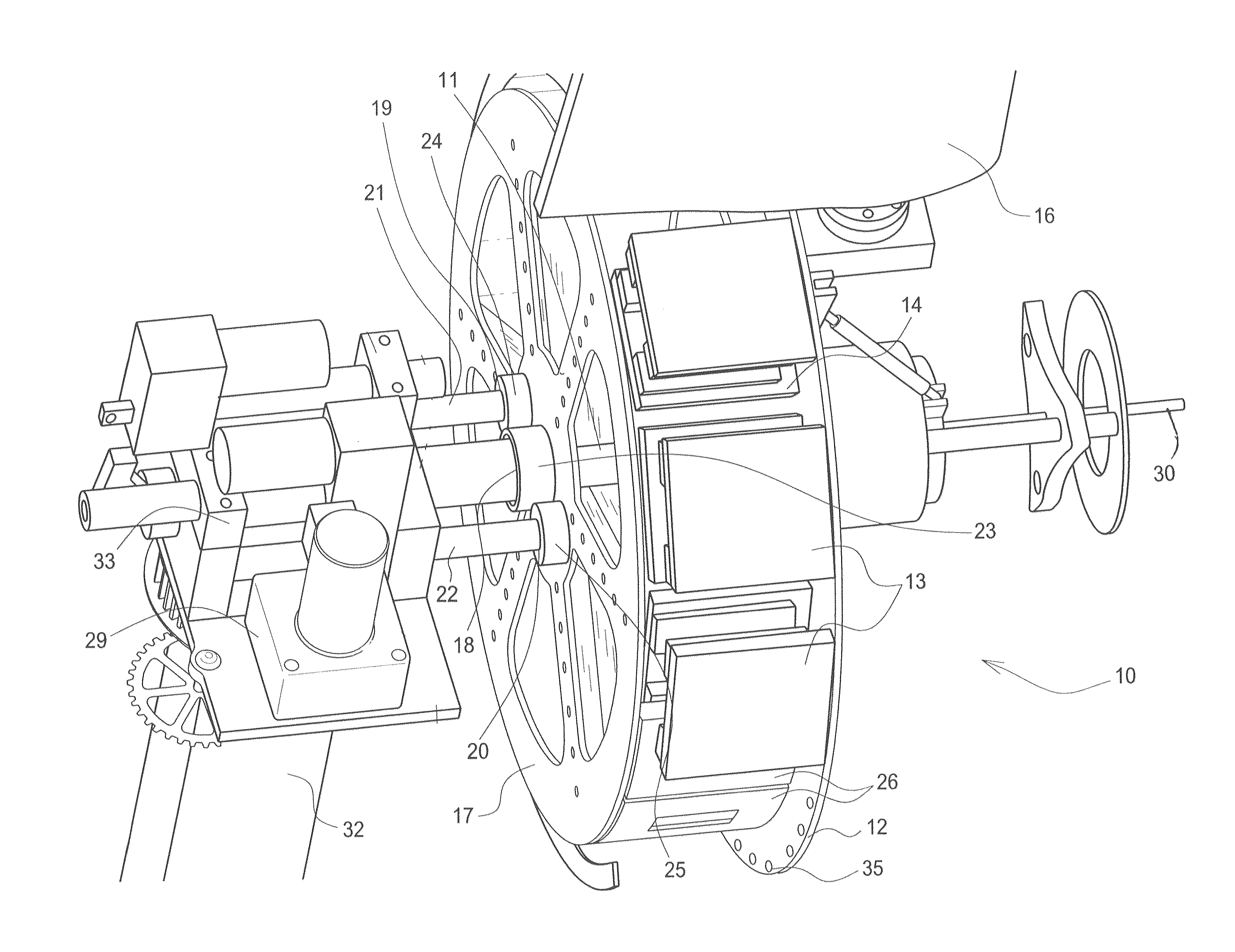
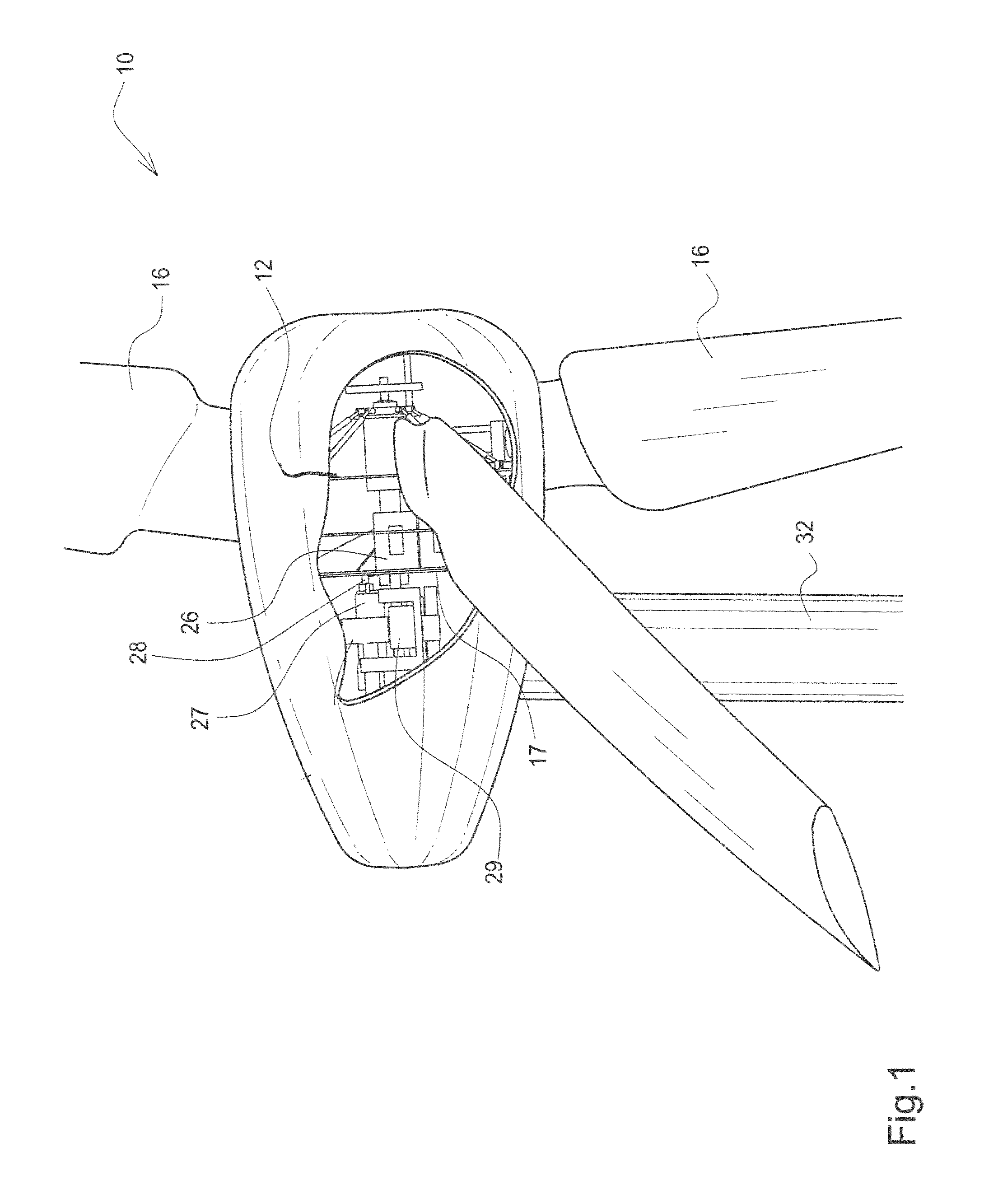
[0020]With reference now to the drawings, and in particular to FIGS. 1 through 5 thereof, a new electrical energy generator embodying the principles and concepts of the present invention and generally designated by the reference numeral 10 will be described.

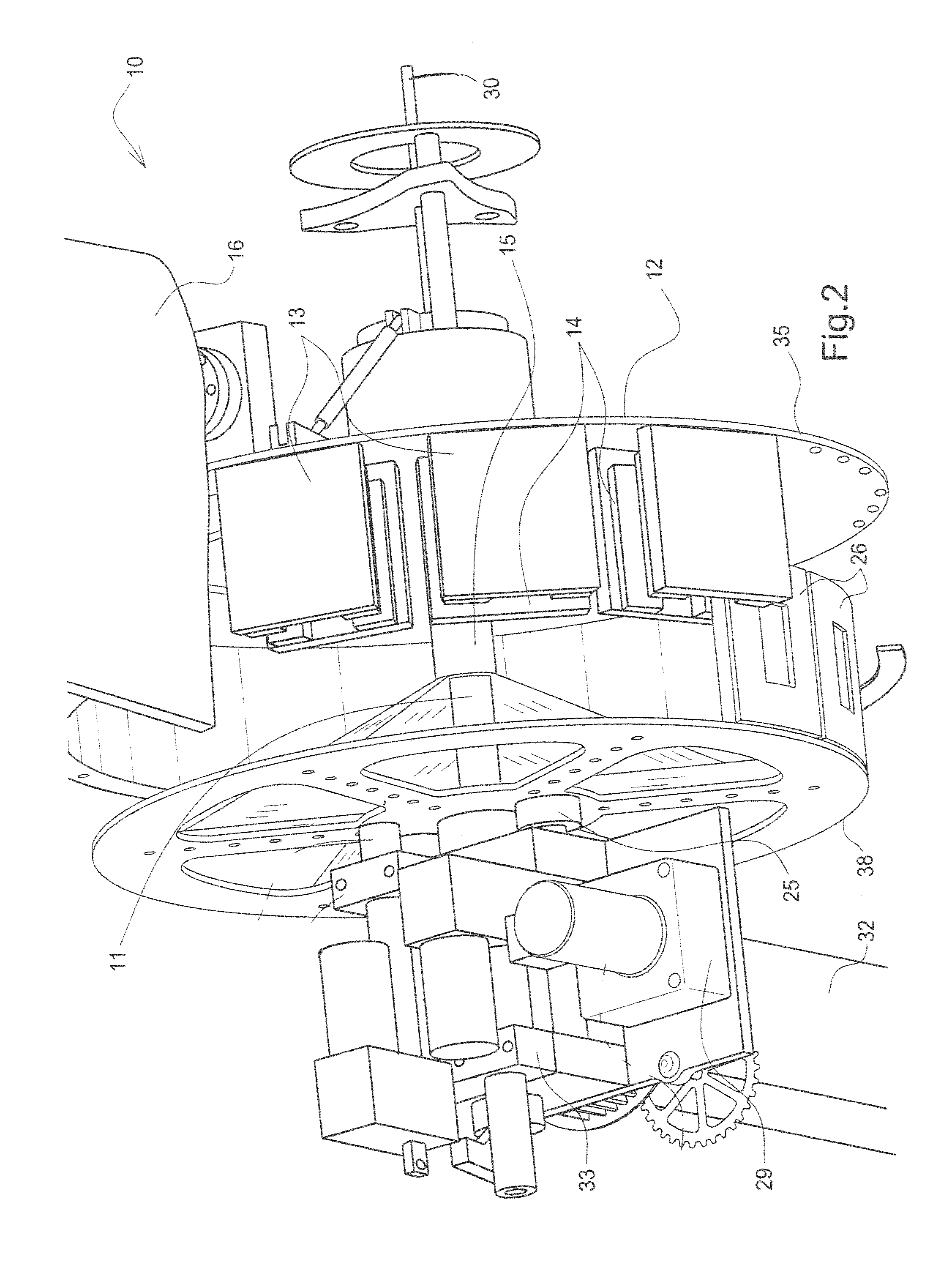
[0021]As best illustrated in FIGS. 1 through 5, the electrical energy generator 10 generally comprises a support assembly 11,32,37 having a support standard 32 and an elongate support member 11 being mounted upon the support standard 32 with brackets 33.

[0022]A rotor assembly 12-16 is rotatably and conventionally disposed upon the support assembly 11,32,37 and has a rotor member 12 being disc-shaped and having a hole 15 being disposed through an axis thereof with a bearing being conventionally disposed in the hole 15 and about the elongate support member 11 with a plurality of vanes 16 being conventionally attached to the rotor member 12 and being movable by air for rotating the rotor assembly 12-16 The rotor assembly 12-16 also ...


PUM


Abstract

An electrical energy generator for generating optimal electrical energy at very low wind speeds and at very high wind speeds. The electrical energy generator includes a support assembly having an elongate support member, and also includes a rotor assembly being rotatably disposed upon the support assembly and having a plurality of vanes being movable by air for rotating the rotor assembly, and further includes a stator assembly being mounted upon the support assembly and including a stator member being movably disposed upon the support assembly for generating energy in cooperation with the rotor assembly, and an assembly for moving the stator member relative to the rotor assembly upon the support assembly.

Description

BACKGROUND OF THE INVENTION[0001]1. Field of the Invention[0002]The present invention relates to generators and more particularly pertains to a new electrical energy generator for generating optimal electrical energy at very low and at very high wind speeds and also by any other external means.[0003]2. Description of the Prior Art[0004]The use of wind generators is known in the prior art. More specifically, wind generators heretofore devised and utilized are known to consist basically of familiar, expected and obvious structural configurations, notwithstanding the myriad of designs encompassed by the crowded prior art which have been developed for the fulfillment of countless objectives and requirements.[0005]The prior art includes wind turbines having stators and rotors being supported upon a support structure with magnets being disposed about the rims of the stators and coils being disposed about the rims of the rotors. Wind-driven vanes are attached to the rotors so that wind wil...

Claims


Application Information

Patent Timeline
IPC IPC(8): H02K21/00
CPCF03D7/0272F03D7/028F03D9/002H02K7/1838H02K21/024H02K21/12F05B2250/41Y02E10/723Y02E10/725F03D9/25Y02E10/72
Inventor SOMERVILLE, CRIS D.
Owner SOMERVILLE CRIS D
Why Eureka
Try Eureka