Illuminating device having fluorescent lamp, display apparatus including the same, and light-diffusing film

a technology of fluorescent lamps and illumination devices, which is applied in the direction of lighting and heating apparatus, discharge tubes luminescnet screens, instruments, etc., can solve the problems of little sense in turning off the lamp, the fluorescent lamp is blinked at 60 hz to 120 hz, and the color quality of the moving image characteristic is not much improved, so as to achieve uniform chromaticity and luminance, improve the color quality of the moving image characteristics, and uniform light-diffusing

Inactive Publication Date: 2012-09-18
SONY CORP
View PDF7 Cites 6 Cited by
  • Summary
  • Abstract
  • Description
  • Claims
  • Application Information

AI Technical Summary

Benefits of technology

[0024]In other words, in high-speed moving image display in which a fluorescent lamp is switched ON and OFF (blinking) at a high frequency, the afterglow generated by turning the lamp OFF last time remains until the next time the lamp is turned ON if the decay time of the phosphor used in the fluorescent lamp is long. Thus, turning the lamp OFF makes little sense. In other words, blinking makes little contribution. Accordingly, in order to improve the color quality among the high-speed moving image characteristics of a liquid crystal device having a backlight that includes a fluorescent lamp, the phosphor used in the fluorescent lamp, in particular, the green phosphor having the largest spectral luminous efficiency, is desired to have a short decay time.
[0030]In view of the above, a illuminating device including a fluorescent lamp that can improve the color quality of the high-speed moving image characteristics, a display apparatus including the illuminating device, and a light-diffusing film for used in the illuminating device are desired.
[0032]According to this structure, the color purity of the white light emitted from the illuminating device is not degraded by the afterglow of the green light even when the fluorescent lamp is blinked at a high frequency, and the chromaticity remains the same. Thus, an illuminating device in which the moving image quality degradation is suppressed can be provided.
[0034]The light-diffusing film having the above-described structure is suitable for use in the illuminating device described above. The light-diffusing film achieves a substantially uniform light-diffusing effect and light having substantially uniform chromaticity and luminance can be emitted.
[0035]A display apparatus of yet another embodiment includes the illuminating device described above. Thus, blinking of emission by switching the backlight ON and OFF can be reliably performed. Thus, the color quality of the moving image characteristics can be improved, and a display apparatus for high-speed moving image display, in particular, a liquid crystal display apparatus, can be provided.

Problems solved by technology

However, blinking the fluorescent lamp at 60 Hz to 120 Hz does not much improve the moving image characteristic if the decay time of the phosphor used in the fluorescent lamp is long.
Thus, turning the lamp OFF makes little sense.

Method used


Image

  • Illuminating device having fluorescent lamp, display apparatus including the same, and light-diffusing film
  • Illuminating device having fluorescent lamp, display apparatus including the same, and light-diffusing film
  • Illuminating device having fluorescent lamp, display apparatus including the same, and light-diffusing film

Examples


embodiments

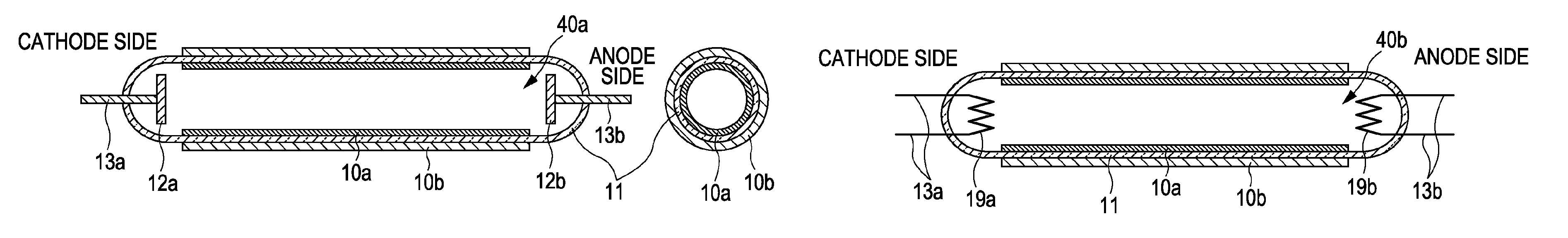
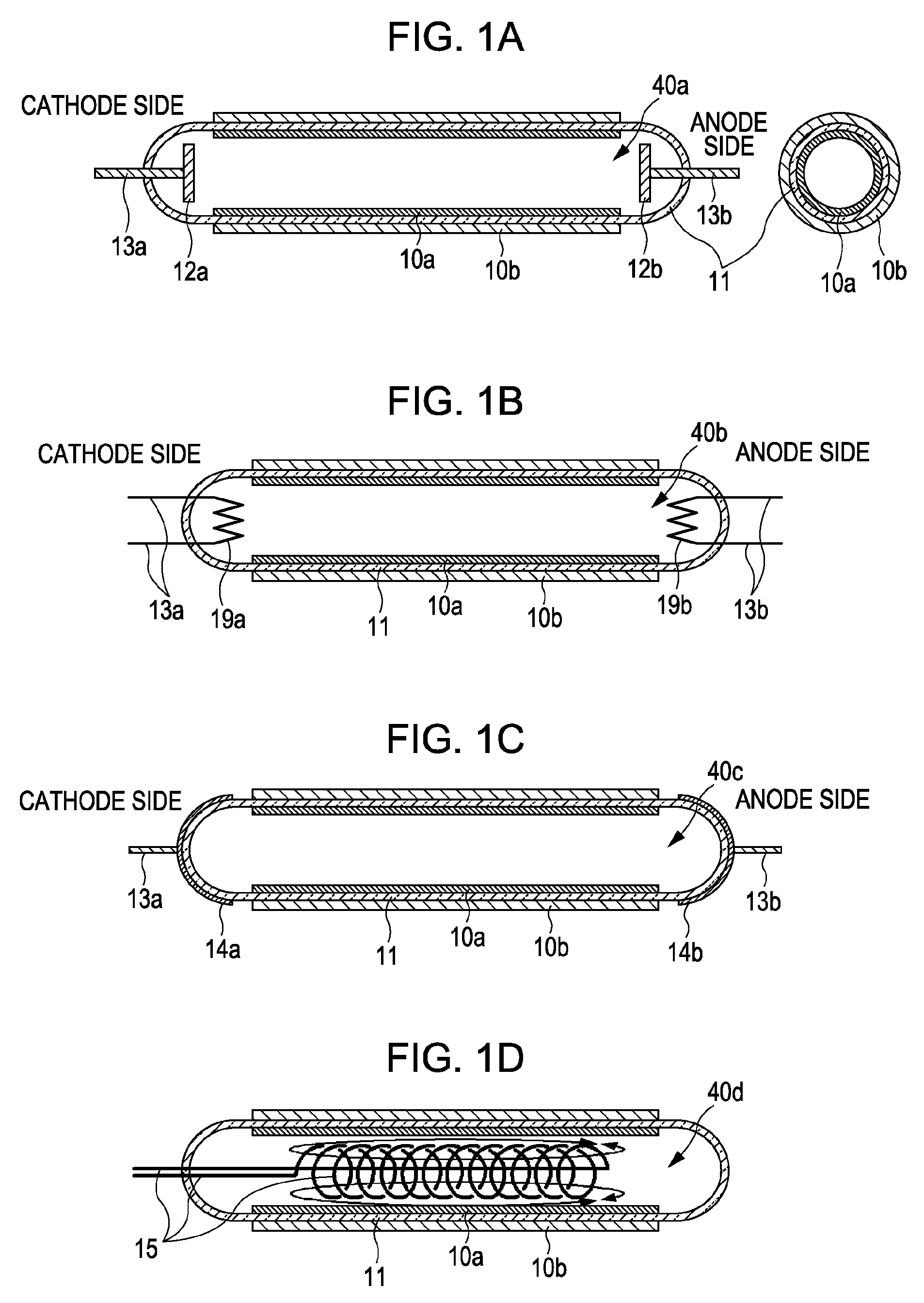
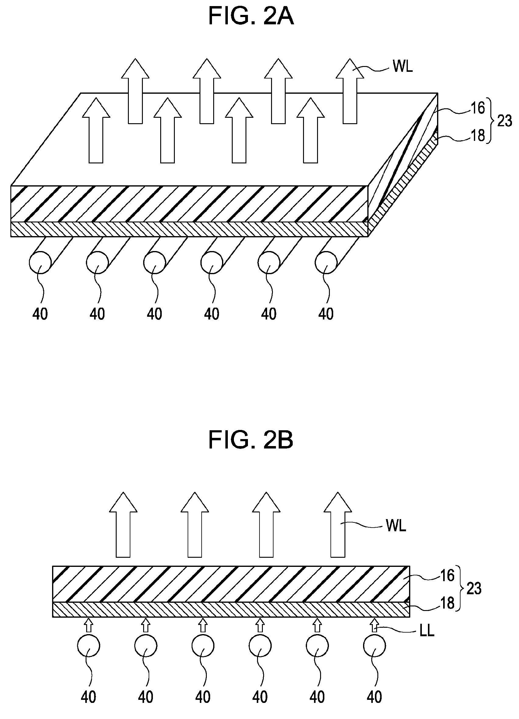
[0081]An illuminating device according to one embodiment has a fluorescent lamp including UV-excitable blue and red phosphors. Phosphor layers containing blue and red phosphors are formed on the inner surface of a fluorescent lamp tube, and a phosphor layer containing a green phosphor having an Eu2+ or Ce3+ luminescent center and a luminescent center wavelength of 500 nm to 570 nm is formed on the outer surface of the fluorescent lamp tube. Blue light emitted from the blue phosphor excites the green phosphor, and white light which is a mixture of blue light, red light, and green light is emitted from the illuminating device. Alternatively, the phosphor layer containing the green phosphor may be formed on a light-diffusing plate instead of the outer surface of the fluorescent lamp tube so that the phosphor layer containing the green phosphor is configured as a separate component from the fluorescent lamp tube.

[0082]A phosphor having a 1 / 10 decay time of 0.2 msec or less is preferably...

example 1

Illuminating Device Having a Diffusion Plate Provided with a Green Phosphor (SrGa2S4:Eu) Layer and Disposed Outside a CCFL

[0194]A binder was prepared by dissolving 6 g of ethyl cellulose in 300 mL of terpineol. To 20 mL of the binder, 5.0 g of a green phosphor (SrGa2S4:Eu) was added to prepare a paste, and the paste was applied on the diffusion plate 16 by printing to form a single layer.

[0195]An illuminating device including the diffusion plate and a CCFL having an inner wall on which a blue phosphor (Srx,Bay,Caz,Mg(1-x-y-z))5(PO4)3Cl:Eu and a red phosphor Y2O3:Eu were applied was made and used as a backlight of a liquid crystal panel. The weight ratio of the blue phosphor (Srx,Bay,Caz,Mg(1-x-y-z))5(PO4)3Cl:Eu to the red phosphor Y2O3:Eu that achieved a white chromaticity point near (0.300, 0.300) when the backlight installed in the liquid crystal panel was turned ON was found by trial-and-error testing, and a mixture of the blue phosphor and the red phosphor was applied on the CCF...

example 2

Illuminating Device Having a Diffusion Plate Provided with a Green Phosphor ((Sr,Ba,Ca,Mg)2SiO4:Eu) Layer and Disposed Outside a CCFL

[0197]The green phosphor (SrGa2S4:Eu) in EXAMPLE 1 was replaced with (Sr,Ba,Ca,Mg)2SiO4:Eu and the 1 / 10 decay time of the green phosphor (Sr,Ba,Ca,Mg)2SiO4:Eu was evaluated.

[0198]As in EXAMPLE 1, a green phosphor (Sr,Ba,Ca,Mg)2SiO4:Eu was applied on the diffusion plate 16, and an illuminating device including this diffusion plate and a CCFL having an inner wall on which a blue phosphor (Srx,Bay,Caz,Mg(1-x-y-z))5(PO4)3Cl:Eu and a red phosphor Y2O3:Eu were applied was made and used as a backlight of a liquid crystal panel. The 1 / 10 decay time of the green phosphor (Sr,Ba,Ca,Mg)2SiO4:Eu was also about 0.2 msec.


PUM


Abstract

An illuminating device includes a fluorescent lamp including a blue phosphor and a red phosphor applied on an inner surface, the fluorescent lamp emitting blue light and red light from the blue phosphor and the red phosphor, respectively; and a green phosphor layer disposed outside the fluorescent lamp, the green phosphor layer containing a green phosphor containing Eu2+ or Ce3+ as a luminescent center. Green light emitted from the green phosphor excited by the blue light is mixed with the red light and the blue light so that white light is emitted from the illuminating device.

Description

CROSS REFERENCES TO RELATED APPLICATIONS[0001]The present invention contains subject matter related to Japanese Patent Application JP 2007-266371 filed in the Japanese Patent Office on Oct. 12, 2007, the entire contents of which are incorporated herein by reference.BACKGROUND OF THE INVENTION[0002]1. Field of the Invention[0003]The present invention generally relates to illuminating devices for use in display apparatuses such as liquid crystal televisions and the like. In particular, the present invention relates to an illuminating device having a fluorescent lamp, suitable for use in a display apparatus such as a liquid crystal television capable of high-speed moving image display, a display apparatus including the illuminating device, and a light-diffusing film used in the illuminating device.[0004]2. Description of the Related Art[0005]Fluorescent lamps are used in televisions and liquid crystal displays (LCDs) for personal computers (PCs). Typically, phosphors that respectively ...

Claims


Application Information

Patent Timeline
Patent Type & Authority Patents(United States)
IPC IPC(8): H01J29/88
CPCC09K11/7731C09K11/7734C09K11/7739C09K11/7787G02F1/133604H01J1/63H01J1/66H01J61/48G02F1/133606G02F2001/133614Y02B20/181Y02B20/00G02F1/133614C09K11/77342
Inventor MORIZAWA, KAZUHIKOLEE, SUNG-KILIGARASHI, TAKAHIROKUSUNOKI, TSUNEO
Owner SONY CORP
Why Eureka
Try Eureka