Optical transmission system

a transmission system and optical transmission technology, applied in the field of optical transmission systems, can solve the problems of waveform distortion that cannot be significantly reduced, signal quality degradation, etc., and achieve the effect of efficient reduction of waveform distortion

Inactive Publication Date: 2012-09-18
FUJITSU LTD
View PDF26 Cites 25 Cited by
  • Summary
  • Abstract
  • Description
  • Claims
  • Application Information

AI Technical Summary

Benefits of technology

[0012]The present invention was created in view of the above circumstances, and an object thereof is to provide an optical transmission system capable of efficiently reducing waveform distortion.

Problems solved by technology

If the dispersion is too small, on the other hand, significant interference of waveforms occurs during the wavelength division multiplex transmission due to crosstalk attributable to FWM (Four Wave Mixing) and also due to XPM (Cross Phase Modulation) of adjacent channels, leading to degradation of the signal quality.
Where distortion is compensated only at one of the transmitting and receiving stations, however, the amount of compensation occasionally becomes large, giving rise to a problem that the waveform distortion cannot be significantly reduced.

Method used


Image

  • Optical transmission system
  • Optical transmission system
  • Optical transmission system

Examples


first embodiment

[0037]the present invention will be now described in detail with reference to the drawings.

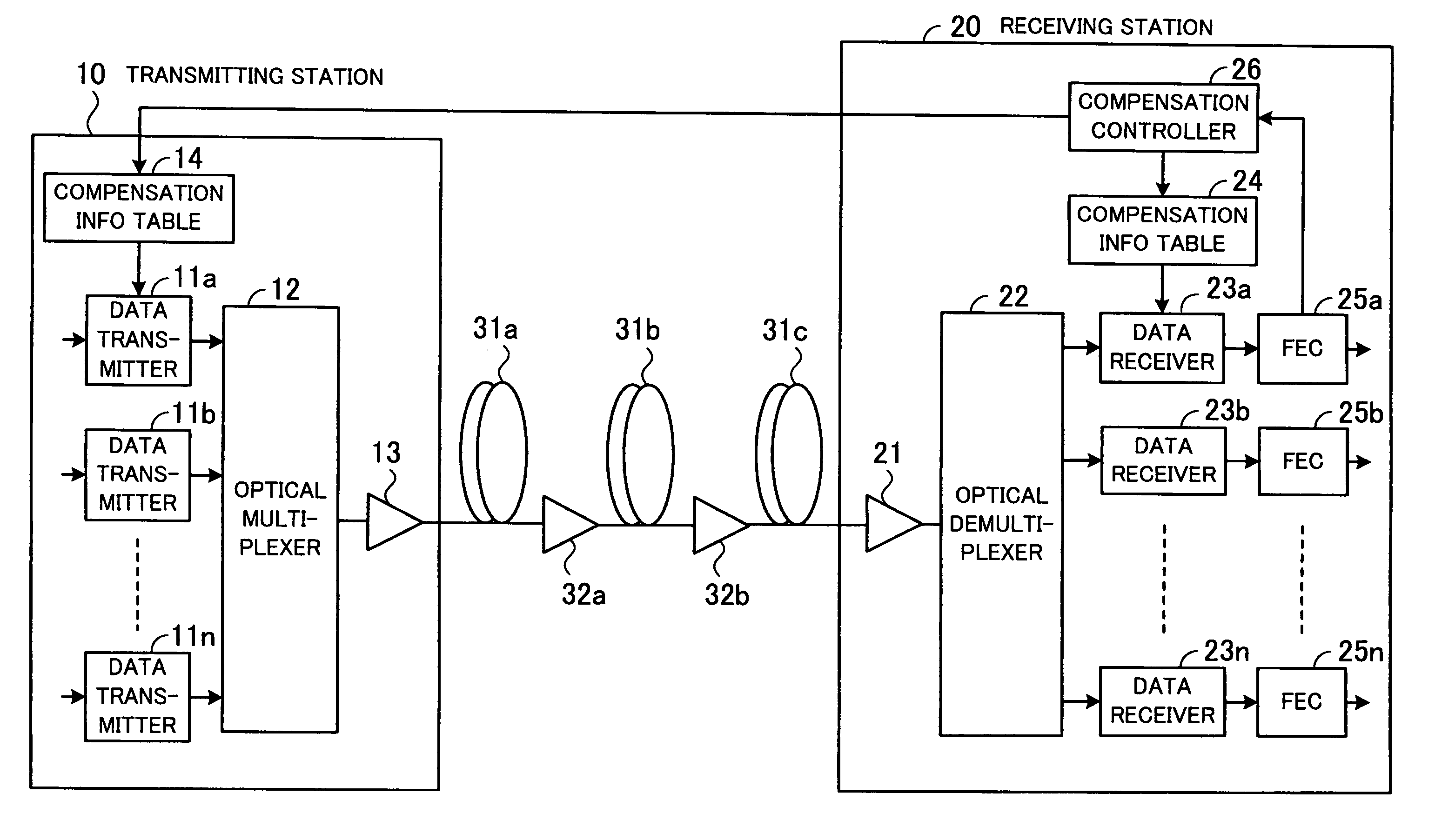
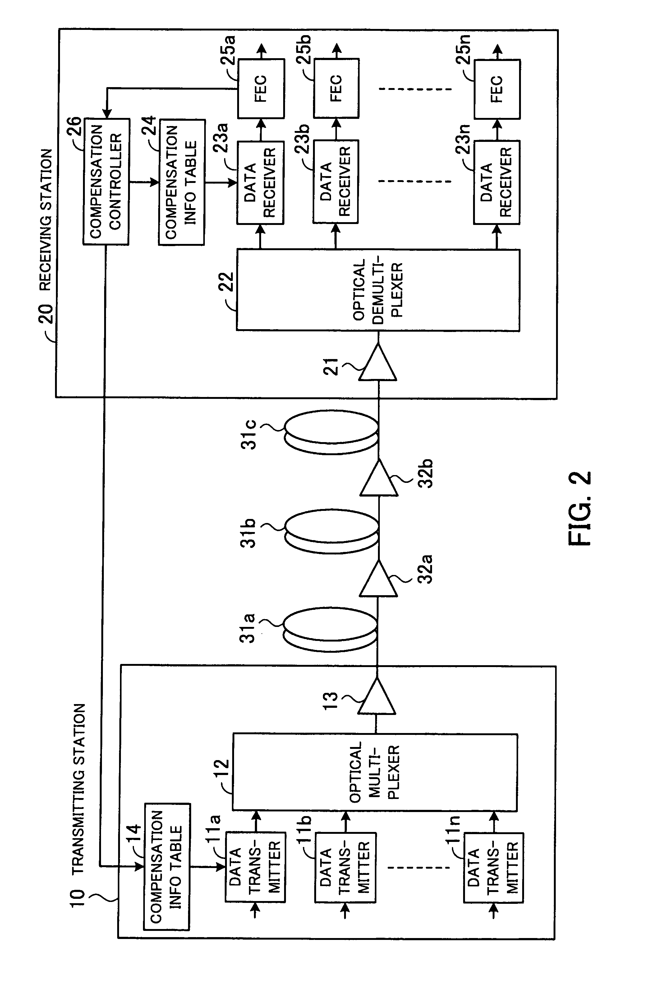
[0038]FIG. 2 illustrates an optical transmission system according to the first embodiment. In FIG. 2, a transmitting station 10 transmits an optical signal, and a receiving station 20 receives the optical signal. The transmitting and receiving stations 10 and 20 are connected to each other by optical fibers 31a, 31b and 31c and repeaters 32a and 32b.

[0039]The transmitting and receiving stations 10 and 20 share in the compensation for SPM-GVD induced distortion caused on the transmission path constituted by the optical fibers 31a, 31b and 31c and the repeaters 32a and 32b. For example, the transmitting station 10 performs distortion compensation covering 70% of the transmission path, and the receiving station 20 performs distortion compensation covering the remaining 30%.

[0040]The share ratio of dispersion compensation is adjusted by looking up the quality of the signal received by the receivi...

second embodiment

[0099]FIG. 9 illustrates an optical transmission system according to the In FIG. 9, like reference numerals refer to like elements also appearing in FIG. 2, and description of such elements is omitted. Also, in FIG. 9, the optical fibers 31a, 31b and 31c and the repeaters 32a and 32b shown in FIG. 2 are omitted.

[0100]A compensation information table 61 holds compensation data for compensating for distortion of the signal waveform of the data transmitter 11a caused under the influence of the signal input to the channel (data transmitter 11b) adjacent to the data transmitter 11a.

[0101]For example, the compensation information table 61 stores amplitude compensation data and phase compensation data that are used to compensate for distortion of the signal waveform of the data transmitter 11a when the signal input to the data transmitter 11b, which is the channel adjacent to the data transmitter 11a, is “000”. Likewise, the compensation information table 61 stores amplitude compensation...

third embodiment

[0127]FIG. 11 illustrates an optical transmission system according to the In FIG. 11, like reference numerals refer to like elements also appearing in FIG. 2, and description of such elements is omitted. Also, in FIG. 11, the optical fibers 31a, 31b and 31c and the repeaters 32a and 32b shown in FIG. 2 are omitted.

[0128]As shown in FIG. 11, the transmitting station 10 additionally includes a polarization combiner 71, and the receiving station 20 additionally includes a polarization separator 72.

[0129]The polarization combiner 71 combines the optical signals output from the data transmitters 11a and 11b such that their polarizations are orthogonal to each other. The optical signals from the data transmitters 11a and 11b have an identical wavelength. Namely, the polarization combiner 71 combines the two modulating signals of an identical wavelength together with their polarizations orthogonalized, thereby making good use of the signal bandwidth.

[0130]The polarization separator 72 sep...


PUM

PropertyMeasurementUnit
lengthaaaaaaaaaa
chromatic dispersionaaaaaaaaaa
dispersionaaaaaaaaaa

Abstract

An optical transmission system capable of efficiently reducing waveform distortion of an optical signal. A transmitting-side distortion compensation coefficient storage of a transmitting station stores transmitting-side distortion compensation coefficients for compensating for waveform distortion of an optical signal to be transmitted to a receiving station. A transmit signal processor performs distortion compensation on the optical signal on the basis of a suitable transmitting-side distortion compensation coefficient stored in the transmitting-side distortion compensation coefficient storage. A transmitter transmits the distortion-compensated signal to a transmission path. A receiver of the receiving station receives the optical signal from the transmission path. A receiving-side distortion compensation coefficient storage stores receiving-side distortion compensation coefficients for compensating for waveform distortion of the optical signal received by the receiver. A received signal processor performs distortion compensation on the received optical signal on the basis of a suitable receiving-side distortion compensation coefficient.

Description

CROSS-REFERENCE TO RELATED APPLICATIONS[0001]This application is based upon and claims the benefits of priority from the prior Japanese Patent Application No. 2008-082310, filed on Mar. 27, 2008, the entire contents of which are incorporated herein by reference.BACKGROUND[0002]1. Field[0003]The present invention relates to optical transmission systems, and more particularly, to an optical transmission system for compensating for waveform distortion of optical signals.[0004]2. Description of the Related Art[0005]In optical communication systems using optical fibers as transmission paths, waveform distortion occurs due to chromatic dispersion, and therefore, design of chromatic dispersion is of great importance. If the amount of chromatic dispersion is too large, optical signal waveforms are distorted under the influence of spectral spread attributable to SPM (Self Phase Modulation), degrading the signal quality. If the dispersion is too small, on the other hand, significant interfere...

Claims


Application Information

Patent Timeline
Patent Type & Authority Patents(United States)
IPC IPC(8): H04B10/00H04B10/2507G02F1/035G02F2/00H04B10/07H04B10/2513H04B10/255H04B10/548H04B10/588H04J14/00H04J14/02
CPCH04B10/2507H04B2210/252H04B2210/254
Inventor NAKAMOTO, HIROSHI
Owner FUJITSU LTD
Why Eureka
Try Eureka