
Transmission power management

a power management and transmission technology, applied in power management, transmission monitoring, wireless commuication services, etc., can solve the problems of wasting network resources, affecting the inability to correctly receive information transmitted on the channel by the receiver, so as to improve the quality of service, increase the network performance, and increase the network resources

Inactive Publication Date: 2012-09-25
ROCKSTAR BIDCO +1
View PDF43 Cites 21 Cited by
  • Summary
  • Abstract
  • Description
  • Claims
  • Application Information

AI Technical Summary

Benefits of technology

[0017]The invention in accordance with an embodiment of the invention has the advantage that the transmission power can be adjusted so that the cell capacity and thus the network resources are increased. This also increases the performance of the network and a better quality of service (QoS) can be provided to the users of the network.

Problems solved by technology

Absolute grants provide an absolute limitation of the maximum amount of uplink resources the UE may use.
However, if the transmission power is set to a too low value, the information transmitted on the channel may not be correctly received by the receiver.
On the other hand, the constant power, as is used for instance on E-AGCH, wastes network resources and creates interference, if it is set to a too high value.

Method used


Image

  • Transmission power management
  • Transmission power management
  • Transmission power management

Examples


Embodiment Construction

[0035]Some embodiments of the invention will now be described in more detail in the framework of the UMTS HSUPA. In this case, the considered radio channel between the UE 109 and the BS 107 is thus a high speed uplink channel, like an E-DCH. The invention could also be applied to other channels or units assuming that an uplink power headroom (UPH) or equivalent value is signalled from the UE 109 to the BS 107. It is to be noted that the invention can equally be applied to other types of communication systems as well.

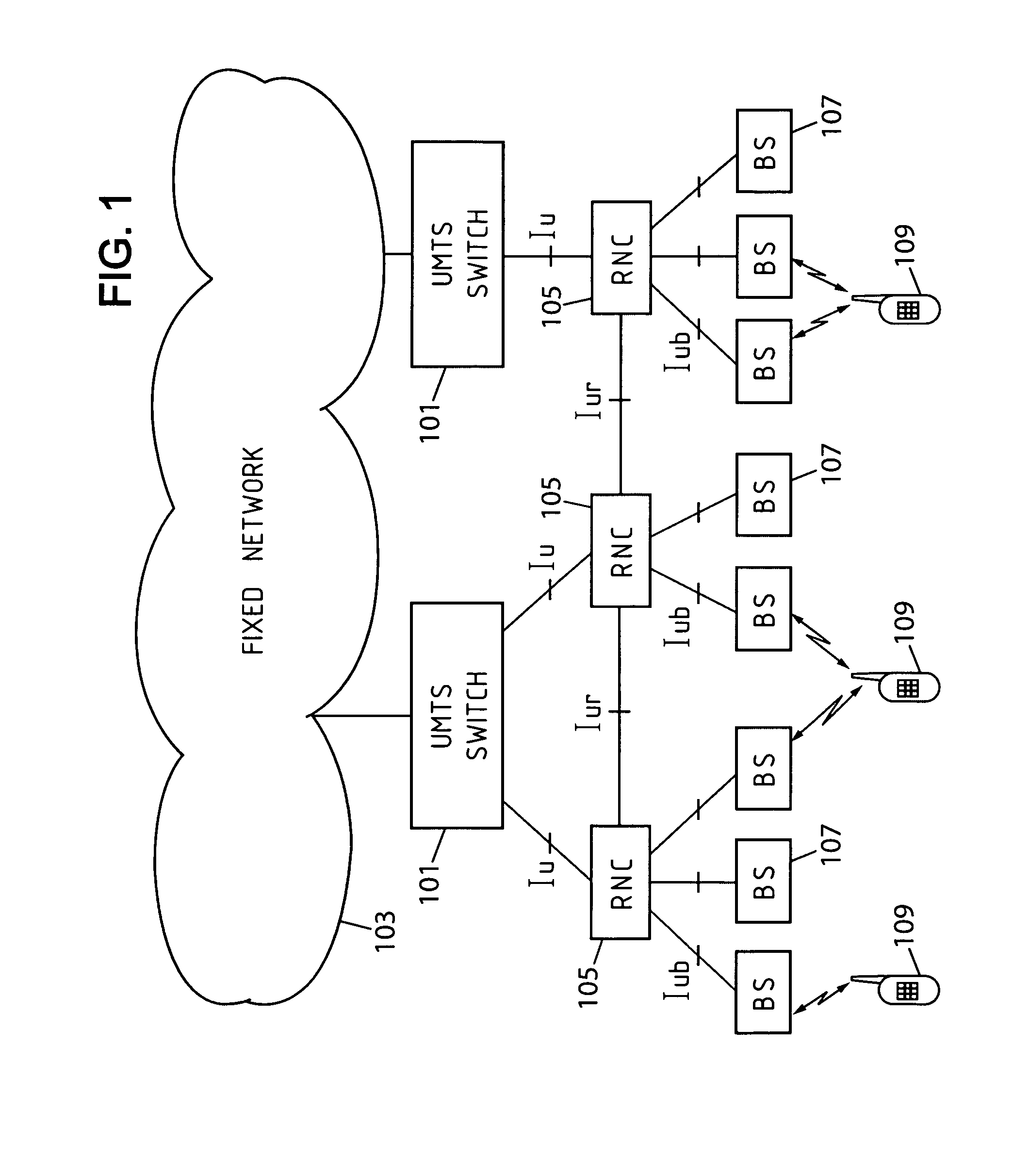
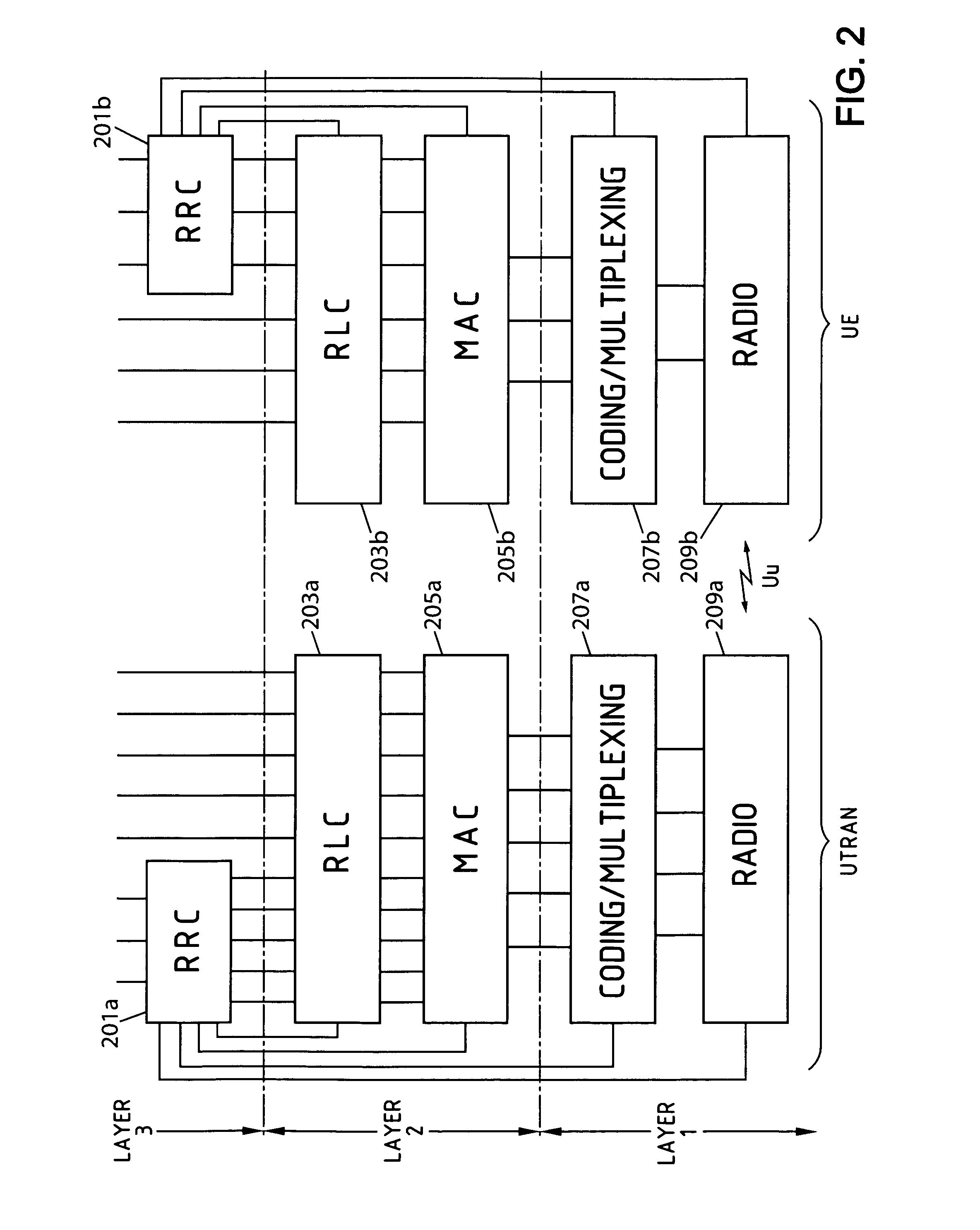
[0036]In FIG. 1, the network elements are arranged to implement corresponding protocols shown in FIG. 3. Furthermore, the BSs 107 are arranged to transmit on E-AGCH.

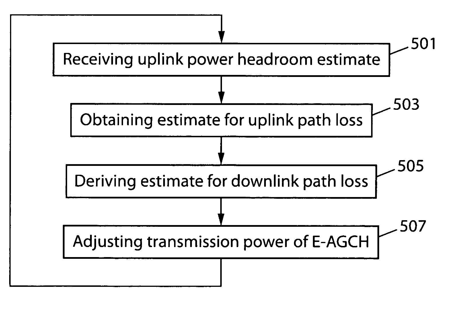
[0037]Next a method for determining transmission power on the E-AGCH is described with reference to FIG. 5 in accordance with an embodiment of the invention. In the context of E-DCH a metric called uplink power headroom (UPH) is determined in the following way:

[0038]UPH=Ptx,m⁢⁢ax,UEPtx,DPCCH,UE,(1)

where Ptx,m...


PUM


Abstract

The present invention relates to a method of adjusting transmission power on a downlink radio channel in a communication system comprising a user equipment and a base station. In the method uplink power headroom is determined by dividing a maximum transmission power of the user equipment by a transmission power of a control channel of the user equipment and the determined uplink power headroom value is sent to the base station. Then uplink path loss estimate is determined between the user equipment and the base station based on the uplink power headroom. Then an estimate for the downlink path loss is derived and finally the transmission power of the downlink radio channel is adjusted taking into account the downlink path loss estimate.

Description

FIELD OF THE INVENTION[0001]The present invention relates to radio transmissions, and more precisely to the transmission power management in a base station of a wireless communication system.BACKGROUND OF THE INVENTION[0002]In the present description, the invention will be described more particularly in its non-limiting application to third generation radio communication networks of the universal mobile telecommunication system (UMTS) type. In this system, the invention finds application within the framework of the high speed uplink packet access (HSUPA) feature being specified by the 3rd Generation Partnership Project (3GPP)—also named “FDD enhanced uplink” in 3GPP terminology, or “E-DCH” according to the transport channel's name. This feature is described particularly in the technical specification TS 25.309, V6.6.0, “FDD Enhanced Uplink; Overall description; Stage 2 (Release 6)”, published in March 2006 by the 3GPP.[0003]FIG. 1 shows the architecture of such a UMTS network. The s...

Claims


Application Information

Patent Timeline
Patent Type & Authority Patents(United States)
IPC IPC(8): H04B7/216H04B7/00H04W52/10H04W52/14H04W52/20H04W52/24H04W52/36
CPCH04W52/143H04W52/242H04W52/367H04W52/10H04W52/20
Inventor JARD, ALEXANDRECORBEL, JEAN-MARCMORETTE, MICHAEL
Owner ROCKSTAR BIDCO
Learn More