Modular fore-end rail assembly for firearms

a module and foreend rail technology, applied in the direction of weapons, butts, sighting devices, etc., can solve the problems of prior art interface rails, multiple sighting devices of military personnel, and need support both on the receiver end and the end of the barrel, so as to prevent any load from entering the barrel, facilitate the removal of the lower portion, and prevent any load from being transferred.

Inactive Publication Date: 2012-10-02
TROY STEPHEN P JR
View PDF27 Cites 45 Cited by
  • Summary
  • Abstract
  • Description
  • Claims
  • Application Information

AI Technical Summary

Benefits of technology

[0010]The fore-end rail assembly includes an upper hand guard, a lower hand guard and a clamping member that combines with the rear portion of the upper hand guard to encircle and clamp onto the barrel nut thereby supporting the entire assembly from the front of the upper receiver and preventing any transfer of load into the barrel.
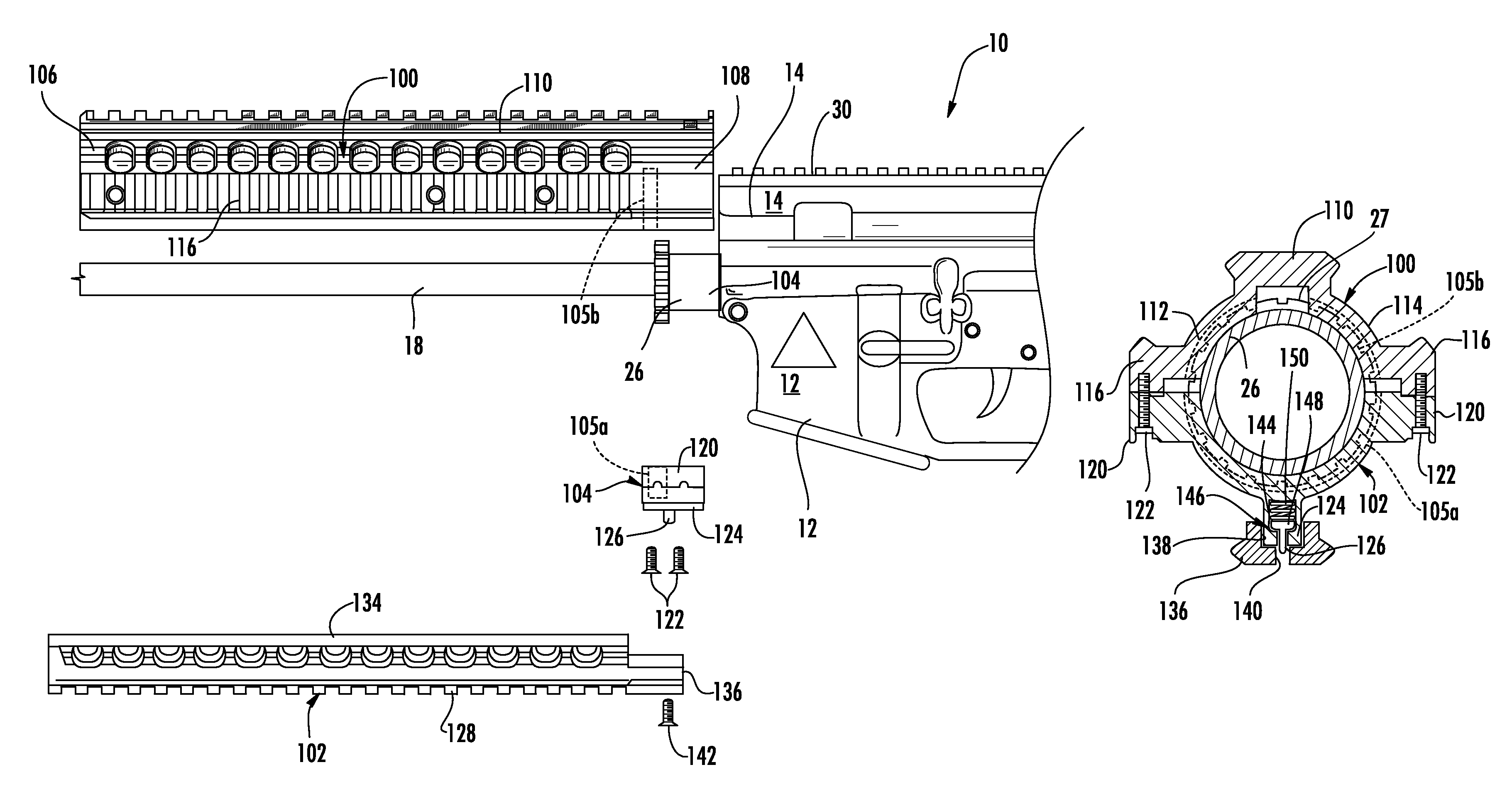
[0011]Additionally, the present invention includes a novel three-piece construction that facilitates removal of the lower portion of the hand guard for access to the barrel without requiring the removal of the entire fore-end rail assembly from the firearm. The lower portion of the hand guard is slidably received into channels formed in the upper hand guard and is retained in its installed position by a spring biased detent located in the clamping member. The lower hand guard is removable by simply depressing the detent and sliding the lower hand guard forward. It can be seen that by providing for the easy removal of the lower hand guard, other auxiliary devices may be mounted to the upper hand guard. For example, an M203 grenade launcher can be mounted to the upper hand guard in place of the lower hand guard portion.
[0012]Therefore, it is an object of the present invention to provide a modular fore-end rail assembly for mounting onto a firearm wherein the assembly is fully supported by the upper receiver of the firearm thereby preventing any transfer of load into the barrel itself. It is a further object of the present invention to provide a modular fore-end rail assembly that mounts onto and is supported by the standard barrel nut found on the M16 / M4 weapons system thereby preventing any transfer of load into the barrel of the weapon. It is still a further object of the present invention to provide a modular fore-end rail assembly that includes a unique construction whereby the lower hand guard assembly is easily mounted onto and removed from the upper hand guard assembly thereby providing easy access to the barrel of the firearm while also facilitating the mounting of additional accessories.

Problems solved by technology

The difficulty is that many military personnel have multiple sighting devices in addition to a variety of lighting devices, accessory handgrips, etc. that could also be attached to the weapon for enhanced use of the weapon.
While there have been many attempts in the prior art to provide additional dovetail rail interfaces, the difficulty found in most of the prior art interface rails is that they require support both on the receiver end as well as at the end of the barrel.
Such load transfer can adversely affect the alignment of the barrel with the upper receiver, which in turn interferes with the reliable function of the weapon.
However in such configurations, the weight of any accessories mounted on the interface rail system is still partially carried by the front end of the barrel.
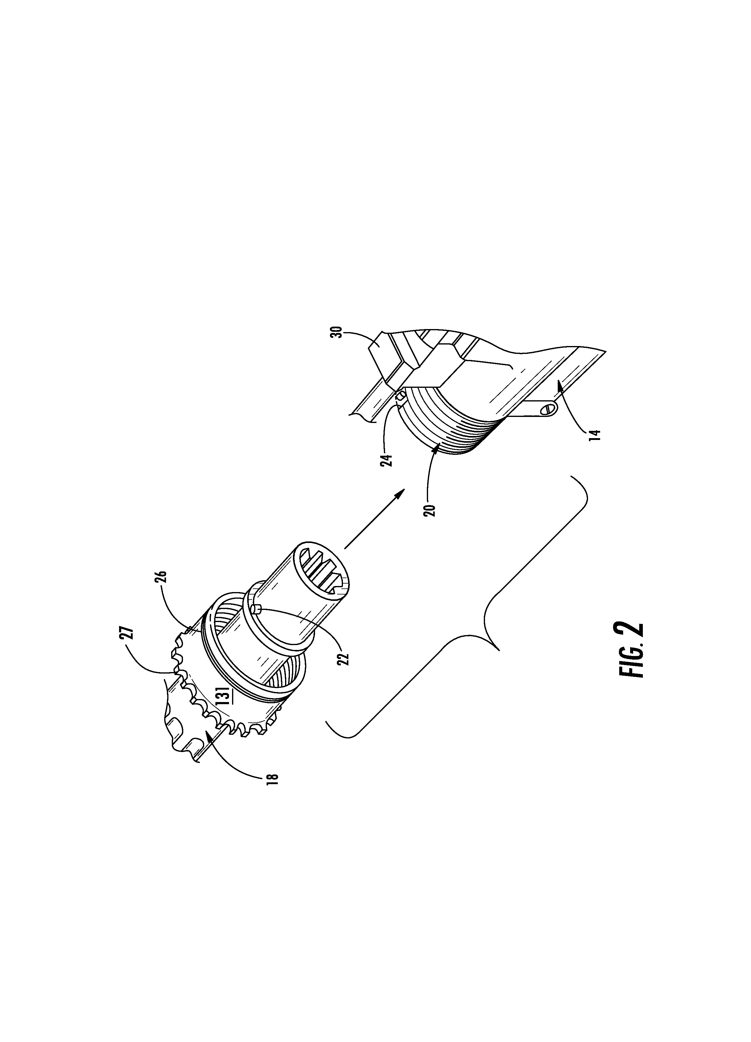
However, many of these devices require removal and replacement of the original barrel nut with a modified barrel nut that includes a means for interfacing and supporting the rail.
Other disadvantages include the fact that frequently these devices are formed as a unitary tubular assembly thereby preventing access to the barrel once the tubular assembly is installed.

Method used


Image

  • Modular fore-end rail assembly for firearms
  • Modular fore-end rail assembly for firearms
  • Modular fore-end rail assembly for firearms

Examples


Embodiment Construction

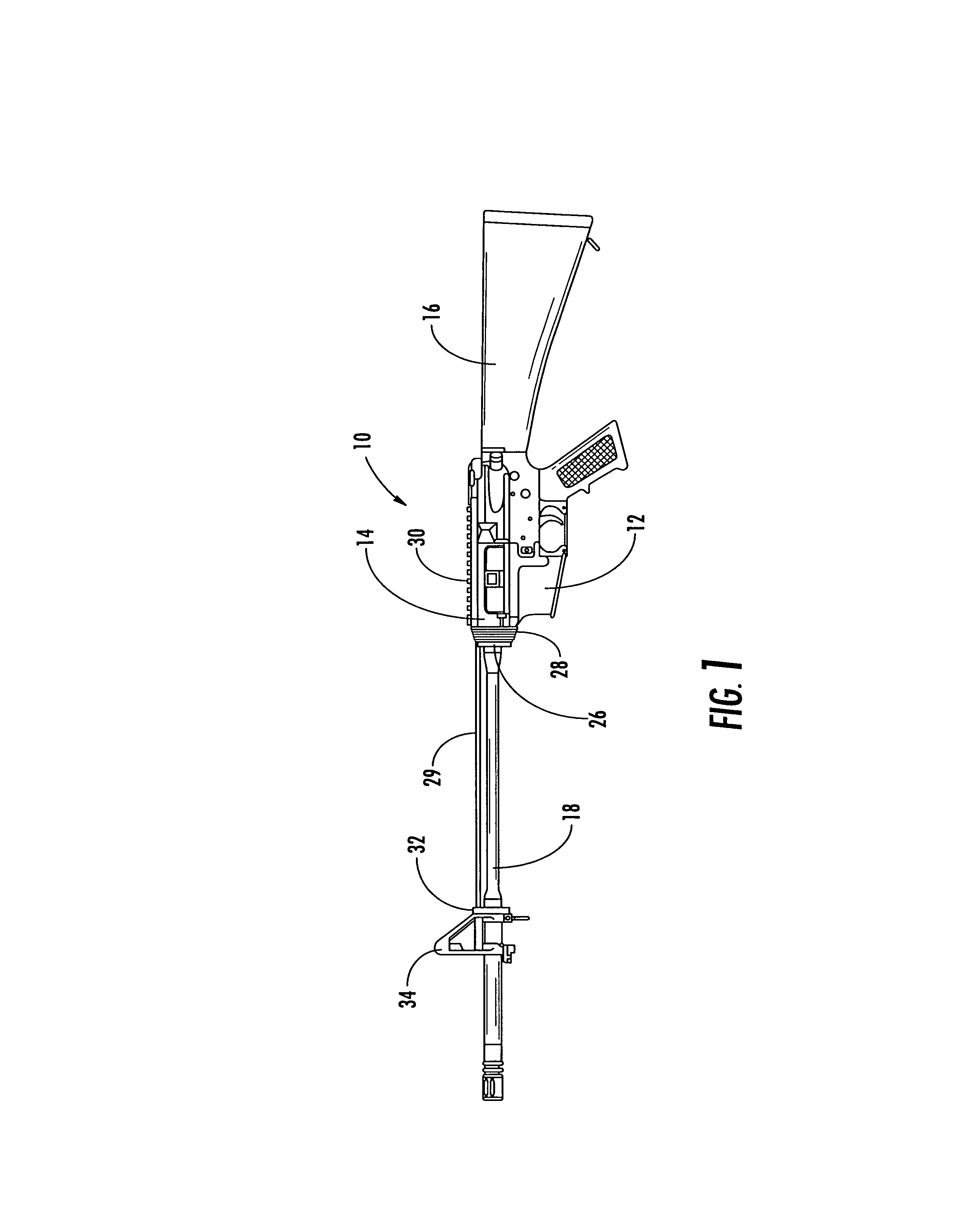
[0023]Now referring to the drawings, the modular fore-end rail assembly of the present invention is shown and generally illustrated in FIGS. 3-8. As can be seen the modular fore-end rail assembly of the present invention generally includes an upper hand guard 100, a lower hand guard 102 and a clamping assembly 104.

[0024]The upper hand guard assembly 100 is the structural element that supports the entire fore-end rail assembly and serves to transfer the loads or additional weight induced by any attachments into the upper receiver 14 of the firearm 10. The upper hand guard 100 is formed generally as the upper half of a tubular enclosure that is configured to encircle the barrel 18 of the firearm 10 when the fore-end rail assembly is installed on the firearm 10 in a mounted position. The upper hand guard 100 has a forward end 106 and a rearward end 108 and a standard dovetail rail 110 extending longitudinally between the forward end 106 and the rearward end 108. The upper hand guard 10...


PUM


Abstract

A modular fore-end rail assembly for mounting onto a firearm includes an upper hand guard, a lower hand guard and a clamping member that combines with the rear portion of the upper hand guard to encircle and clamp onto the barrel nut thereby supporting the entire assembly from the front of the upper receiver and preventing any transfer of load into the barrel. The lower portion of the hand guard is slidably received into channels formed in the upper hand guard and is retained in its installed position by a spring biased detent located in the clamping member. The lower hand guard is removable by simply depressing the detent and sliding the lower hand guard forward. By providing for the easy removal of the lower hand guard, other auxiliary devices may be mounted to the upper hand guard.

Description

CROSS-REFERENCE TO RELATED APPLICATIONS[0001]This application is related to and claims priority from earlier filed U.S. Provisional Patent Application No. 60 / 644,890, filed Jan. 18, 2005, the contents of which are incorporated herein by reference.BACKGROUND OF THE INVENTION[0002]The present invention relates generally to a modular fore-end rail assembly for firearms. More specifically, the present invention relates to a modular fore-end rail assembly for retrofitting a firearm that includes an upper hand guard portion, which is clamped around and supported by the barrel nut and a removable lower hand guard portion that is mounted onto the upper hand guard portion to fully surround the firearm barrel.[0003]In the general field of combat and commercial weaponry, there is a broad range of accessories available for mounting onto standard firearms in order to upgrade the capability of these weapons. Of particular interest in the context of upgrade accessories is the M16 / M4 weapon system ...

Claims


Application Information

Patent Timeline
Patent Type & Authority Patents(United States)
IPC IPC(8): F41A21/48F41A11/02F41G1/38
CPCF41C23/16
Inventor SAMSON, SCOTT W.LANKARGE, KENNETH
Owner TROY STEPHEN P JR
Why Eureka
Try Eureka