Translating aperture adjustment for a recessed luminaire

a technology of recessed luminaires and apertures, which is applied in the direction of fixed installation, lighting and heating equipment, lighting support devices, etc., can solve the problems of problems with parallel adjustment of recessed luminaires, and similar problems, so as to improve the adjustability of recessed luminaires

Active Publication Date: 2012-10-02
ABL IP HLDG
View PDF4 Cites 59 Cited by
  • Summary
  • Abstract
  • Description
  • Claims
  • Application Information

AI Technical Summary

Benefits of technology

[0006]In an implementation of the present invention, a multi-directional adjustment system for a recessed luminaire improves the adjustability of recessed luminaires prior to the installation of a finished ceiling (or wall). The adjustment system incorporates features that allow adjustment of the recessed luminaire in at least two directions relative to structural framing members, which are generally parallel to each other. The adjustment directions of the adjustment system include (i) an adjustment direction parallel to the framing members and (ii) an adjustment direction perpendicular to the framing members.
[0008]The adjustment system includes a stationary plate, an adjustable plate, and a locking component (such as a locking screw). The adjustable plate has a plurality of guides that are movably attached to corresponding guide slots of the stationary plate. The adjustable plate is secured to the stationary plate via the locking screw. The positional relationship between the stationary plate and the adjustable plate is controlled by the locking screw. During manufacturing and initial installation, the locking screw is positioned (or nesting) into a formed area of the stationary plate. The stationary plate and the adjustable plate allow the recessed luminaire to be adjusted parallel to the framing members.
[0012]In another aspect of our invention, a mounting assembly includes a stationary plate for supporting a recessed fixture and having a plurality of linear guide slots. Telescoping mounting bars are fixed to building structure framing members and allow adjustability of the stationary plate in a direction generally perpendicular to a pair of structural framing members. An adjustable plate has a plurality of guide-receiving holes received in a linear movable manner within a corresponding one of the linear guide slots. A locking member is adjustably secured in one of the linear guide slots such that linear movement of the adjustable plate is prevented relative to the stationary plate when the locking member is in a locked position, linear movement of the adjustable plate being allowed relative to the stationary plate in a direction generally parallel to the structural framing members when the locking member is in an adjustable position.
[0013]In another aspect of our invention, a mounting assembly for a recessed fixture includes a stationary plate having a plurality of linear guide slots, and a first pair of telescoping bars attached to the stationary plate along a first edge. A second pair of telescoping bars is attached to the stationary plate along a second edge, the second edge being parallel to the first edge. A first pair of mounting feet and a second pair of mounting feet are attached respectively to the first pair of telescoping bars and the second pair of telescoping bars for rigidly mounting the respective telescoping bars to a pair of parallel structural framing members. The telescoping bars allow adjustment of the stationary plate in a perpendicular direction relative to the structural framing members. An adjustable plate is mounted to the stationary plate via a plurality of linear guides, each of the linear guides being linearly movable within a corresponding linear guide slot of the plurality of linear guide slots. A locking member is attached in one of the plurality of linear guide slots, the locking member preventing movement between the stationary plate and the adjustable plate in a locked position, the locking member allowing linear movement between the stationary plate and the adjustable plate in an adjustable position. The linear movement between the stationary plate and the adjustable plate is in a direction parallel to the structural framing members and is achievable when the mounting feet are rigidly mounted to the structural framing members.

Problems solved by technology

Accordingly, parallel adjustment of the recessed luminaire can be problematic because the procedure is time consuming and labor intensive.
Problems with parallel adjustment of the recessed luminaire are especially present when only slight adjustments in position are desired or when electrical connections to the recessed luminaire are already in place (when the parallel adjustment is required).
Similar problems may also be present in installation of other devices that are similarly installed to the building framing.

Method used


Image

  • Translating aperture adjustment for a recessed luminaire
  • Translating aperture adjustment for a recessed luminaire
  • Translating aperture adjustment for a recessed luminaire

Examples


Embodiment Construction

[0026]Although the invention will be described in connection with certain preferred embodiments, it will be understood that the invention is not limited to those particular embodiments. On the contrary, the invention is intended to include all alternatives, modifications and equivalent arrangements as may be included within the spirit and scope of the invention as defined by the appended claims.

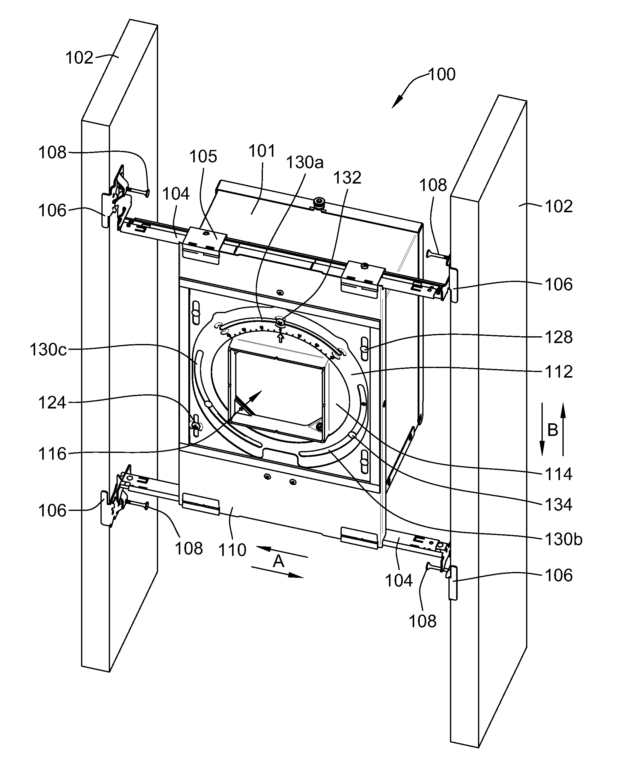
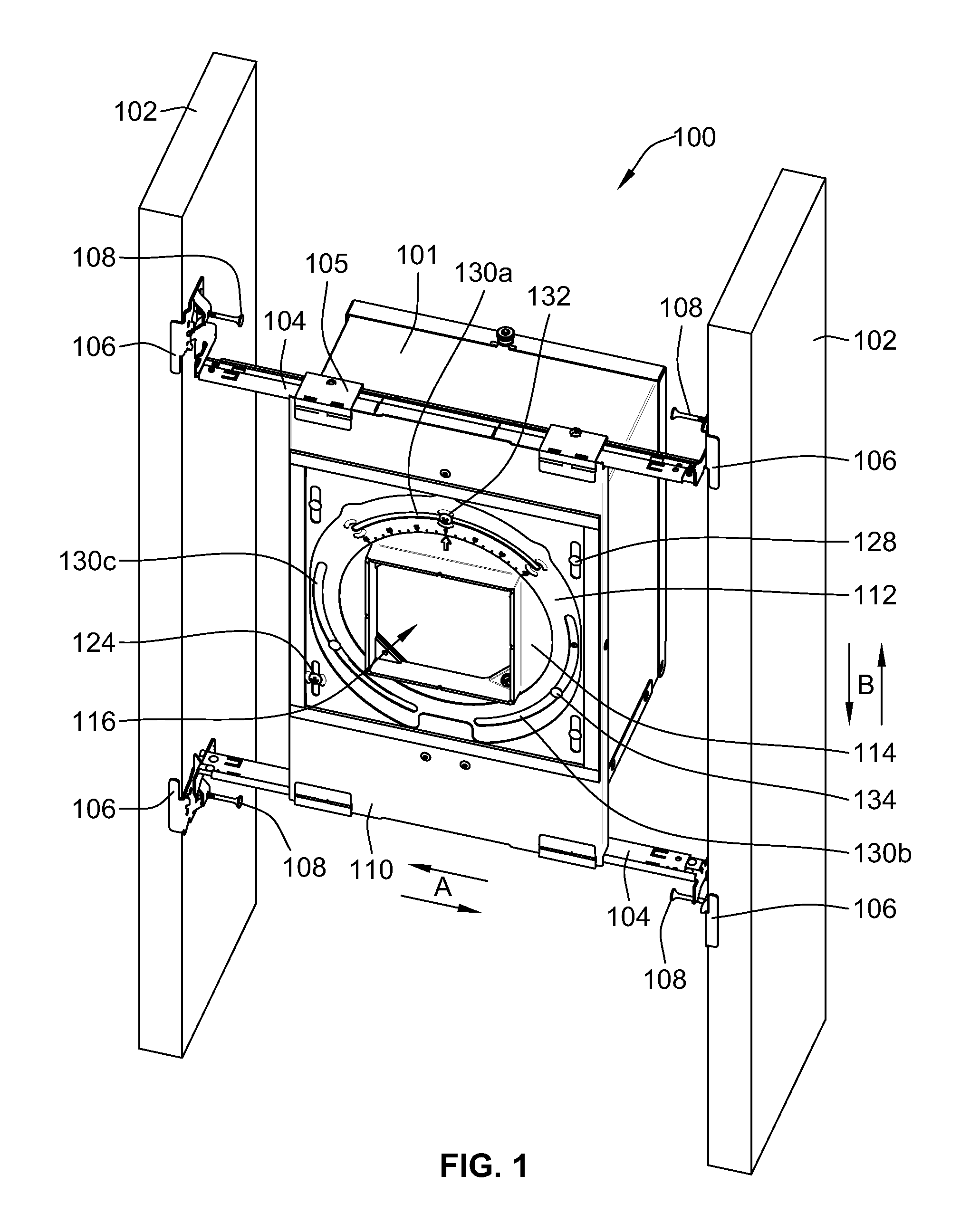
[0027]Referring to FIG. 1, a recessed fixture in the form of a recessed luminaire 100 includes a luminaire housing 101 that is mounted to a pair of structural framing members 102. In other embodiments, for example, the recessed fixture can also be an audio speaker, an electrical fan, or an electrical box. The electrical box can be, for example, a junction box, an outlet box, or a switch box. The structural framing members 102 are typical support members in a building and can include wood and / or steel framing members. The framing members 102 are separated by a distance commonly referred to as ...


PUM


Abstract

A mounting assembly includes a stationary plate for supporting and linearly adjusting a recessed fixture in a parallel direction relative to structural framing members. Telescoping mounting bars are fixed to a building structure and allow adjustability of the stationary plate in a direction generally perpendicular to structural framing members. An adjustable plate has a plurality of linear guides received in a linear movable manner within a corresponding one of linear guide slots of the stationary plate. A linear locking member is adjustably secured in one of the linear guide slots such that linear movement of the adjustable plate is prevented relative to the stationary plate when the linear locking member is in a locked position, linear movement of the adjustable plate being allowed relative to the stationary plate in a direction parallel to the structural framing members when the linear locking member is in an adjustable position.

Description

FIELD OF THE INVENTION[0001]This invention is directed generally to recessed lighting systems, and, more particularly, to a multi-directional adjustment system for the aperture of a recessed fixture.BACKGROUND OF THE INVENTION[0002]Typically, prior to installation of a finished ceiling, a recessed luminaire (or light fixture) is secured to wood and / or steel framing of a building using telescoping bars that cover common spacing between parallel framing members. For example, the telescoping bars cover a joist spacing in the range of about 16 inches-24 inches or a T-Bar spacing in the range of about 24 inches.[0003]After attachment to the building framing, the recessed luminaire can be adjusted perpendicular to the framing members by sliding it along the telescoping bars. However, parallel adjustment relative to the framing members requires complete detachment of the recessed luminaire from the building framing, followed by repositioning and re-attachment of the recessed luminaire. Acc...

Claims


Application Information

Patent Timeline
Patent Type & Authority Patents(United States)
IPC IPC(8): F21V15/00
CPCF21V21/048F21V21/14F21V21/34
Inventor FRYZEK, AARON P.STAUNER, JOESCHUBERT, JOHN
Owner ABL IP HLDG
Why Eureka
Try Eureka