Installation for high pressure compression with several stages

a high-pressure compression and installation technology, applied in the direction of pumps, mechanical equipment, liquid fuel engines, etc., can solve the problems of increasing the space requirement of the installation, increasing the installation reaction rate, and increasing the cost of the installation

Active Publication Date: 2012-10-02
ATLAS COPCO CREPELLE
View PDF6 Cites 6 Cited by
  • Summary
  • Abstract
  • Description
  • Claims
  • Application Information

AI Technical Summary

Benefits of technology

[0018]As the different compressors are turned on together, it becomes possible to keep the pressure prevailing between each of the different compressors constant or practically constant, such that the fluctuations of the gas pressure at the output of a multi-stage compressor according to the invention are more or less minimal.
[0019]An additional advantage of a multi-stage compression installation according to the invention, in which the different compressors are controlled such that they are driven simultaneously, is that the quantity of gas to be provided between the two compressors is comparatively minimal, since the consumption of compressed gas by one compressor can always be compensated for by supplying the compressed gas via the compressor of the preceding stage.
[0020]This reduced quantity of gas to be provided between the different compressors of a multi-stage compressor according to the invention, compared to that of a known multi-stage compressor, is advantageous in that the first tank can be made less voluminous and can even be omitted, which results in smaller and less expensive multi-stage compression installations.

Problems solved by technology

A disadvantage of a high-pressure compressor installation of the known type is that this installation reacts relatively slowly to major fluctuations in the compressed gas consumption.
Another disadvantage of a known multi-stage compression installation is that the first tank between the two compressors must be relatively large in order to prevent all the gas in the first tank from being consumed, at the time the excess pressure compressor is being loaded, before the first compressor has been loaded.
It is clear that a large tank of this type, provided between the compressors, increases the space requirement of said compression installation which, as a consequence, will also be more expensive.

Method used


Image

  • Installation for high pressure compression with several stages
  • Installation for high pressure compression with several stages

Examples


Embodiment Construction

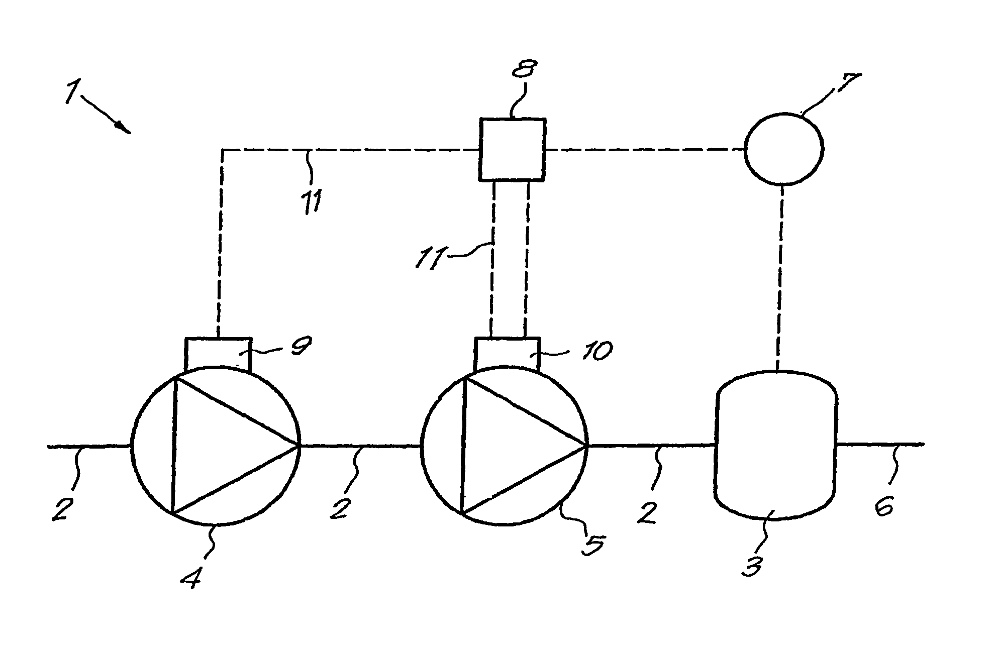
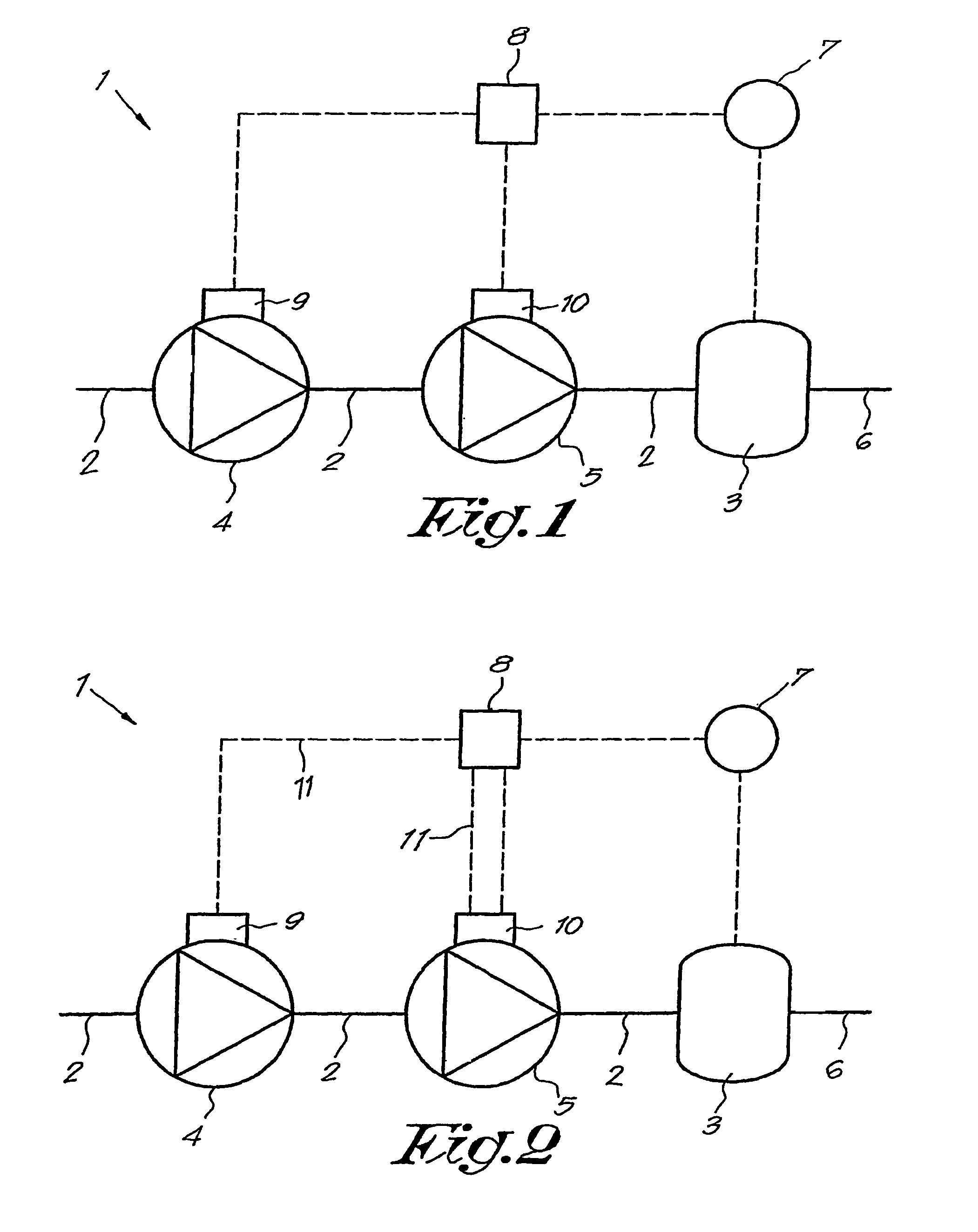
[0025]As represented in FIG. 1, a high-pressure multi-stage compression installation 1 according to the invention is mainly formed of a main gas pipe 2 which opens in a buffer 3 and in which, in this case, two volumetric compressors 4 and 5 are mounted in series.

[0026]The first compressor 4 is for example a screw-type compressor which serves as a low-pressure compression stage, whereas the second compressor 5, also called the excess pressure compressor, is for example a piston compressor which serves as high-pressure compression stage.

[0027]The above-mentioned buffer 3 can be made in the shape of a tank or the like, connected to a user network 6 and in which are preferably provided means 7 which make it possible to regulate the gas pressure prevailing in the tank, and which are connected to a control panel 8, for example an electronic panel.

[0028]Naturally, the above-mentioned means 7 which are designed to regulate the pressure can also be mounted, if desired, at the output of the m...


PUM


Abstract

A multi-stage compression installation is formed of a main pipe (2) emerging in a baffle plate (3), where at least two compressors (4, 5) are mounted in series each having its own drive member (9, 10). The installation is equipped with a system for determining the pressure at the output of the main pipe (2), the installation being connected to a control box (8). Typically, the control box (8) is connected to at least two of the drive members (9, 10) of the compressors (4, 5) and ensures monitoring of the compressors such that the latter rotate jointly whether charged or uncharged. Thus, the compressors (4, 5) are jointly charged based on the pressure prevailing in the baffle plate (3), such that the charging of the compressor representing the overpressure stage, the compressor(s) of the lower compression stages are automatically and jointly charged.

Description

BACKGROUND[0001]1. Field of the Invention[0002]The present invention concerns a multi-stage high-pressure compression installation formed of at least two compressors connected in series by means of at least one pipe.[0003]2. Related Art[0004]This type of high-pressure installation is used for example in the production of PET bottles, whereby the use of compressed gas with a pressure of more than 2000 kPa is required.[0005]It is known, in order to use gas pressures of 2000 kPa or more, to mount two volumetric compressors in series and to provide a first gas tank at the output of the first compressor, whereby the output of the tank is connected to the inlet of the second compressor which is part of what is called the excess pressure compressor.[0006]At the output of the aforesaid excess pressure compressor is in this case preferably provided a second tank which serves as a buffer for a user network.[0007]In a known multi-stage compressor of this type, the drive of the first compressor...

Claims


Application Information

Patent Timeline
Patent Type & Authority Patents(United States)
IPC IPC(8): F04B41/06
CPCF04B25/00F04B41/02F04B41/06F04B49/065F04C23/001F04C23/005F04C28/02F04B2205/05F04C18/16F04C28/08F04C2270/18F04C2270/56
Inventor LELONG, PATRICK MARCEL AUGUSTINMAGITS, HANS THEO
Owner ATLAS COPCO CREPELLE
Why Eureka
Try Eureka