Image forming apparatus

a technology of forming apparatus and forming tube, which is applied in the direction of electrographic process apparatus, instruments, corona discharge, etc., can solve the problems of image quality deterioration, etc., and achieve the effect of improving image quality and preventing fogging

Inactive Publication Date: 2012-10-02
OKI DATA CORP
View PDF6 Cites 2 Cited by
  • Summary
  • Abstract
  • Description
  • Claims
  • Application Information

AI Technical Summary

Benefits of technology

[0009]According to the aspect of the invention, when the unoperated period is equal to or greater than the threshold, the image carrier is operated in the idling operation for the predetermined idling time while the post unoperated period image formation preparation voltage, which is different from the standard image formation voltage, is applied to the given one or more of the image forming elements. Therefore, the charge level of the developer and the surface potential of the image carrier can be maintained in preferable ranges. This prevents fogging caused by long unoperated periods and improves the image quality.

Problems solved by technology

However, in such a conventional printer, as an unoperated period which is the time period from an end of a print job to a beginning of a subsequent print job, become longer the image quality may deteriorate due to fogging, which is a phenomenon in which toner adheres in non-image areas on a paper sheet.

Method used


Image

  • Image forming apparatus
  • Image forming apparatus
  • Image forming apparatus

Examples


first embodiment

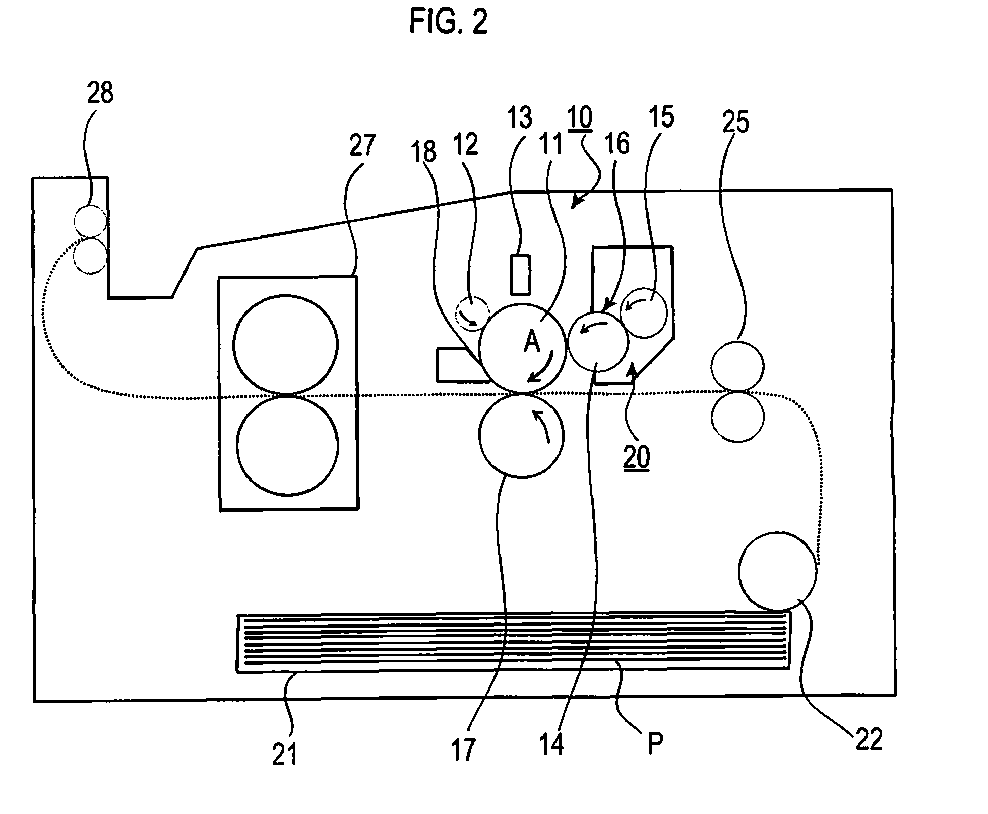
[0022]FIG. 2 is a conceptual diagram of a printer according to a

[0023]As shown in FIG. 2, image forming unit 10 includes photosensitive drum 11 serving as an image carrier, charging roller 12 serving as a charged member or a charging unit provided to contact with photosensitive drum 11 and configured to uniformly charge a surface of photosensitive drum 11, developing unit 20 configured to develop an image by applying toner or a developer to an electrostatic latent image serving as a latent image formed on a surface of photosensitive drum 11 so as to form a toner image or a developer image, and cleaning blade 18 serving as a cleaning member configured to collect toner remaining on photosensitive drum 11 after an image transfer.

[0024]Developing unit 20 includes developing roller 14 serving as a developer carrier provided to contact with photosensitive drum 11, toner supply roller 15 serving as a developer supplier provided to contact with developing roller 14 and configured to charge ...

second embodiment

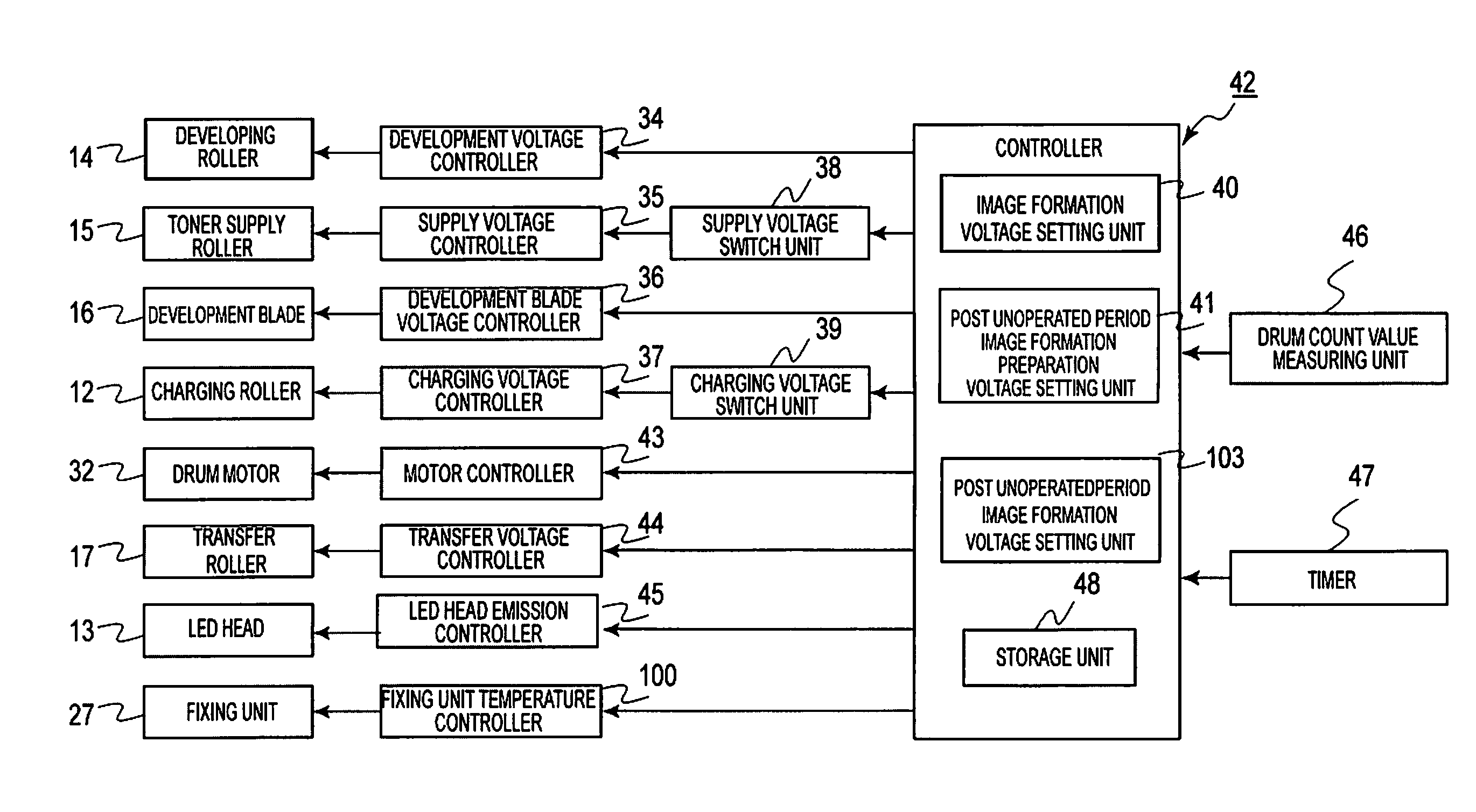
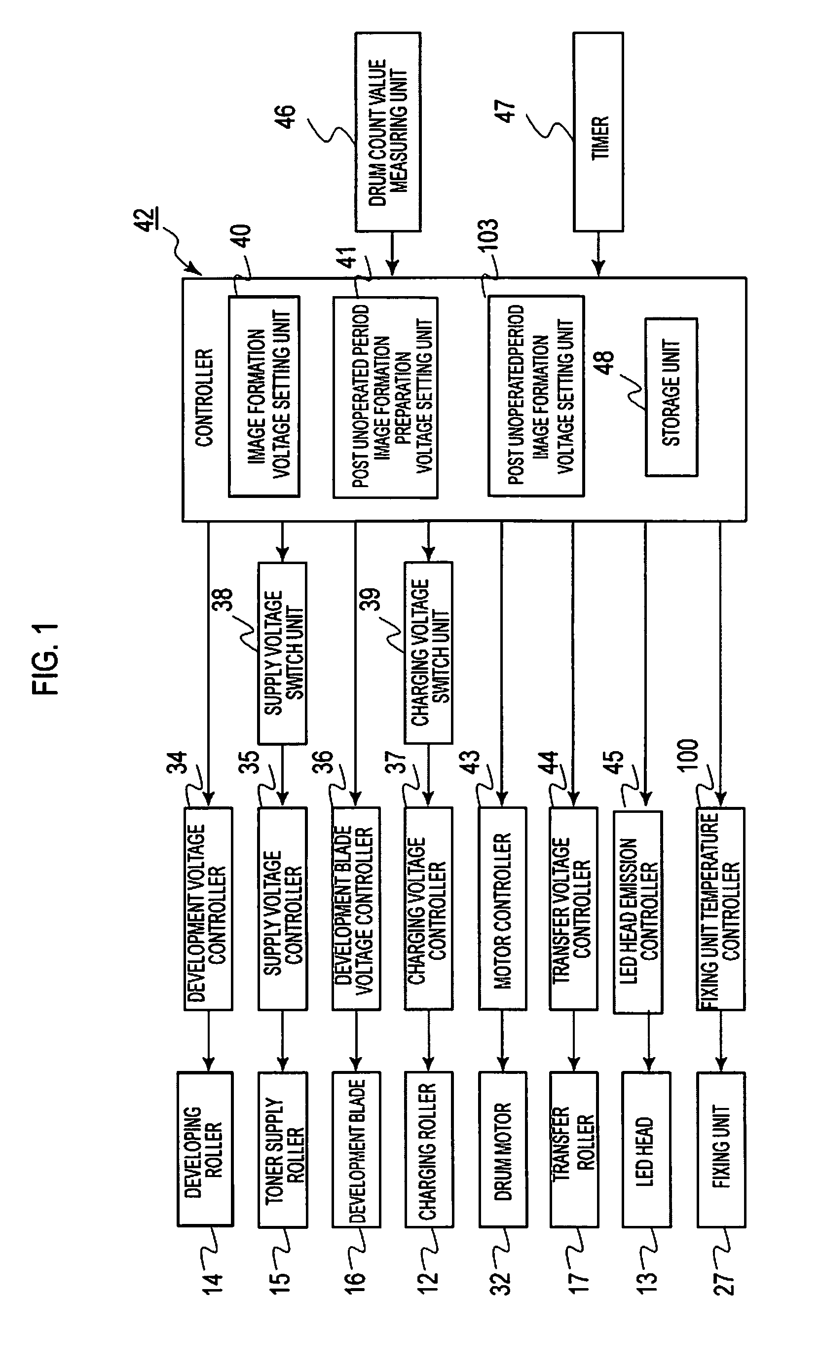
[0098]FIG. 9 is a control block diagram of a printer of the

[0099]In this embodiment, a printer has fixing unit temperature detection unit 101 which is disposed at a predetermined position in fixing unit 27. Fixing unit temperature detection unit 101 detects temperature of fixing unit 27, which is referred to as fixing unit temperature, and sends it to controller 42. Controller 42 reads the fixing unit temperature and records it to storage unit 48.

[0100]In this embodiment, the printer does not have an auxiliary power source such as a battery and the like and it is assumed that the printer is turned off after the printer is left unoperated.

[0101]FIG. 10 is a diagram showing a transition of the fixing unit temperature according to the second embodiment. In FIG. 10, the horizontal axis indicates the unoperated period and the vertical axis indicates the fixing unit temperature.

[0102]In the embodiment, the fixing unit temperature is set to 170° C. during a printing; however, this setting ...


PUM


Abstract

An image forming apparatus includes an image forming unit having image forming elements and a fixing unit. The image forming elements includes an image carrier, a charging unit, a developer carrier, and a developer supplier. The image forming apparatus further includes a post unoperated period image formation preparation processor operable to, when the unoperated period, which is a time period from an end of an image forming operation to a start of a subsequent image forming operation is equal to or greater than a threshold, perform an idling operation to rotate the image carrier while applying a post unoperated period image formation preparation voltage, which is different from a normal image formation voltage, to a given one or more of the image forming elements.

Description

CROSS REFERENCE TO RELATED APPLICATIONS[0001]This application claims priority based on 35 USC 119 from prior Japanese Patent Application No. P2008-238559 filed on Sep. 17, 2008, entitled “Image Forming Apparatus”, the entire contents of which are incorporated herein by reference.BACKGROUND OF THE INVENTION[0002]1. Field of the Invention[0003]The present invention relates to an image forming apparatus.[0004]2. Description of Related Art[0005]Regarding a conventional image forming apparatus such as a printer, a copying machine, a facsimile machine and a multifunctional machine, in a printer as an example, an exposure unit exposes light on a photosensitive drum on which a charging unit uniformly charges electricity to form an electrostatic latent image, a developing unit develops the electrostatic latent image to form a toner image on the photosensitive drum, and then the toner image is transferred onto a paper sheet and fixed thereon.[0006]The developing unit has a developing roller c...

Claims


Application Information

Patent Timeline
Patent Type & Authority Patents(United States)
IPC IPC(8): G03G15/06
CPCG03G15/5008
Inventor OZEKI, FUMITAKA
Owner OKI DATA CORP
Why Eureka
Try Eureka