Medical instrument for grasping surgical suture material

a medical instrument and surgical suture technology, applied in the field of medical instruments for grasping surgical suture materials, can solve the problems of being too large to be able, and achieve the effect of convenient operation

Active Publication Date: 2012-10-09
KARL STORZ GMBH & CO KG
View PDF14 Cites 246 Cited by
  • Summary
  • Abstract
  • Description
  • Claims
  • Application Information

AI Technical Summary

Benefits of technology

[0004]Consequently it is the object of this invention to provide a medical instrument for grasping surgical suture material that is both easy to operate and allows secure grasping and guiding of the suture material.
[0006]The result of the inventive configuration of the only partly coverable indentation in the rigid jaw member is that the grasped suture material, with the tool closed, is positioned in the indentation of the rigid jaw member to move in a U shape around the pivotable jaw member. The shaped winding of the suture material makes it possible for the suture material to glide through the jaw members when there is a sufficient grip at the same time to allow for precise positioning of the suture material.
[0008]According to an advantageous embodiment of the invention, it is proposed that the pivotable jaw member is tapered in such a way that, with the tool in closed position, the indentation configured in the rigid jaw member is freely accessible on both sides of the pivotable jaw member. As a result of the narrower configuration of the pivotable jaw member in relation to the rigid jaw member, and in particular in relation to the width of the indentation configured in the rigid jaw member, the advantageous U-shaped winding of the grasped suture material around the pivotable jaw member and through the indentation is achieved.

Problems solved by technology

With this known instrument it is possible to catch the suture material well, but the recess configured in the rigid jaw member is too large to be able to guide the suture material precisely to the suturing position that is to be configured.

Method used


Image

  • Medical instrument for grasping surgical suture material
  • Medical instrument for grasping surgical suture material
  • Medical instrument for grasping surgical suture material

Examples


Embodiment Construction

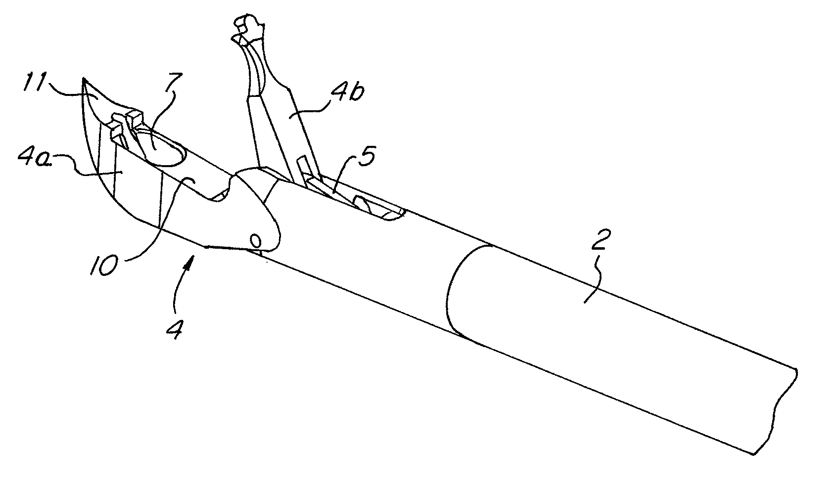
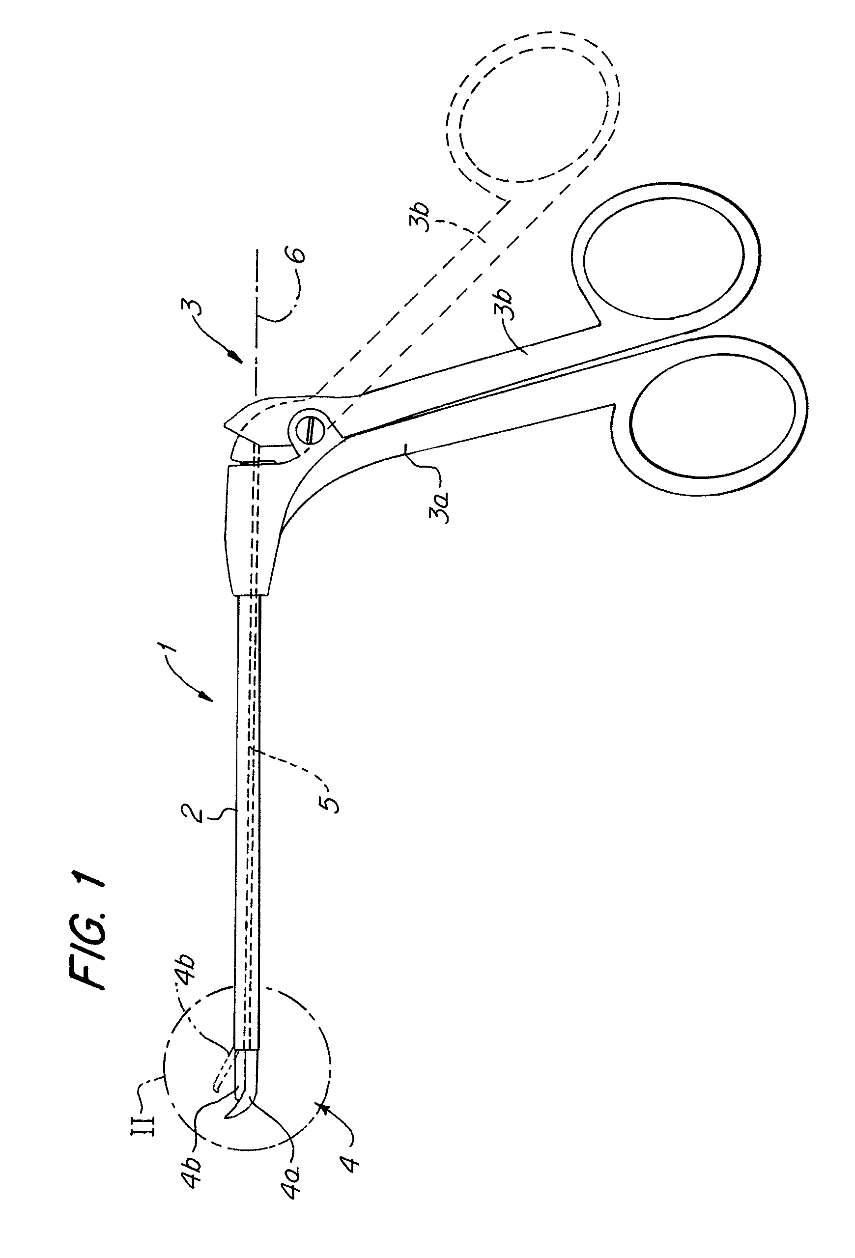
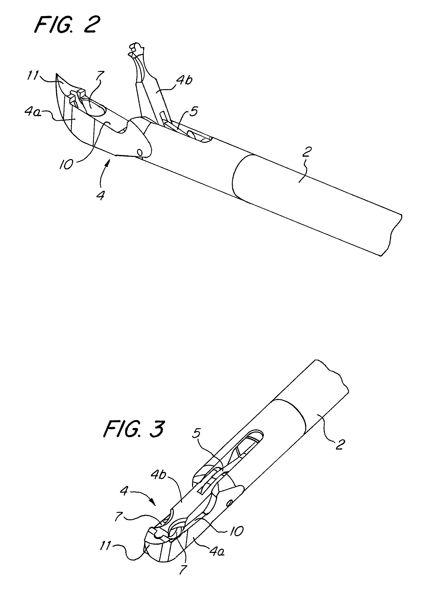
[0023]FIG. 1 shows a medical instrument configured for grasping surgical suture material.

[0024]The instrument 1, shown only schematically, consists essentially of a hollow shaft 2, on whose proximal end a handle 3 is position, which consists of a rigid gripping member 3a and a gripping member 3b that can pivot with respect to the rigid gripping member 3a. Positioned on the distal end of the shaft 2 is a tool 4, which consists of one rigid jaw member 4a and one jaw member 4b that can pivot with respect to the rigid jaw member 4a. Which of the two gripping members 3a or 3b of the handle 3 is configured to be pivotable or otherwise movable is irrelevant to the functioning of the medical instrument 1.

[0025]As can further be seen from FIG. 1, the pivotable jaw member 4b of the tool 4 and the pivotable gripping member 3b of the handle 3 are in active connection with one another by means of an actuating element 5 that is positioned to slide axially in the hollow shaft 2, in such a way that...


PUM


Abstract

A medical instrument for grasping surgical suture material, with a shaft on whose proximal end a handle is positioned consisting of at least two gripping members and on whose distal end a tool is positioned consisting of a rigid jaw member and a pivotable jaw member and where the pivotable jaw member can be pivoted with respect to the rigid jaw member for opening and closing with a moveably configured gripping member of the handle, for which purpose the pivotable jaw member and the moveable gripping member are in active connection with one another by means of an actuating element mounted in the shaft. To create a medical instrument that is both easy to operate and makes possible a safe grasping and guiding of the suture material, it is disclosed that in the rigid jaw member there should be configured an indentation that opens toward the pivotable jaw member and that can be covered, with the tool in closed position, only in the center area by the pivotable jaw member.

Description

CROSS-REFERENCE TO RELATED APPLICATIONS[0001]The present application claims priority of German patent application No. 10 2009 010 101.2 filed on Feb. 24, 2009, the content of which is incorporated herein by reference.FIELD OF THE INVENTION[0002]The invention relates to a medical instrument for grasping surgical suture material, with a shaft on whose proximal end a handle is positioned consisting of at least two gripping members and on whose distal end a tool is positioned consisting of a rigid jaw member and a pivotable jaw member and where the pivotable jaw member can be pivoted with respect to the rigid jaw member for opening and closing by means of a moveably configured gripping member of the handle, for which purpose the pivotable jaw member and the moveable gripping member are in active connection with one another by means of an actuating element mounted in the shaft.BACKGROUND OF THE INVENTION[0003]This type of medical suture-grasping instrument is employed in endoscopic surge...

Claims


Application Information

Patent Timeline
Patent Type & Authority Patents(United States)
IPC IPC(8): A61B17/00A61B17/04
CPCA61B17/0483A61B2017/2926
Inventor GERBER, CHRISTIANOBERLAENDER, MARTINBERBERICH, SASCHA
Owner KARL STORZ GMBH & CO KG
Why Eureka
Try Eureka