
Differential signal transmission device

a transmission device and signal technology, applied in the direction of waveguide type devices, digital transmission, multiple-port networks, etc., can solve the problems of unsatisfactory specification and low voltage at the receiving terminal

Inactive Publication Date: 2012-10-09
HON HAI PRECISION IND CO LTD
View PDF4 Cites 0 Cited by
  • Summary
  • Abstract
  • Description
  • Claims
  • Application Information

AI Technical Summary

Benefits of technology

[0004]Clock signals are significant for an electronic device to synchronously activate components in the electronic device. A number of differential clock signal pairs from a differential clock signal generator should be equal to a number of receiving terminals when the differential clock signal pairs are transmitted by a common signal transmission device. For example, the differential clock signal generator just can provide two differential clock signal pairs to two receiving terminals. If the number of the receiving terminals is more than two, voltages at the receiving terminals may be too low and thereby unsatisfied to a required specification. Additionally, each of the receiving terminals should be grounded via a resistor when the differential clock signal pairs are transmitted by the common signal transmission device, which is costly.

Problems solved by technology

If the number of the receiving terminals is more than two, voltages at the receiving terminals may be too low and thereby unsatisfied to a required specification.
Additionally, each of the receiving terminals should be grounded via a resistor when the differential clock signal pairs are transmitted by the common signal transmission device, which is costly.

Method used


Image

  • Differential signal transmission device
  • Differential signal transmission device
  • Differential signal transmission device

Examples


Embodiment Construction

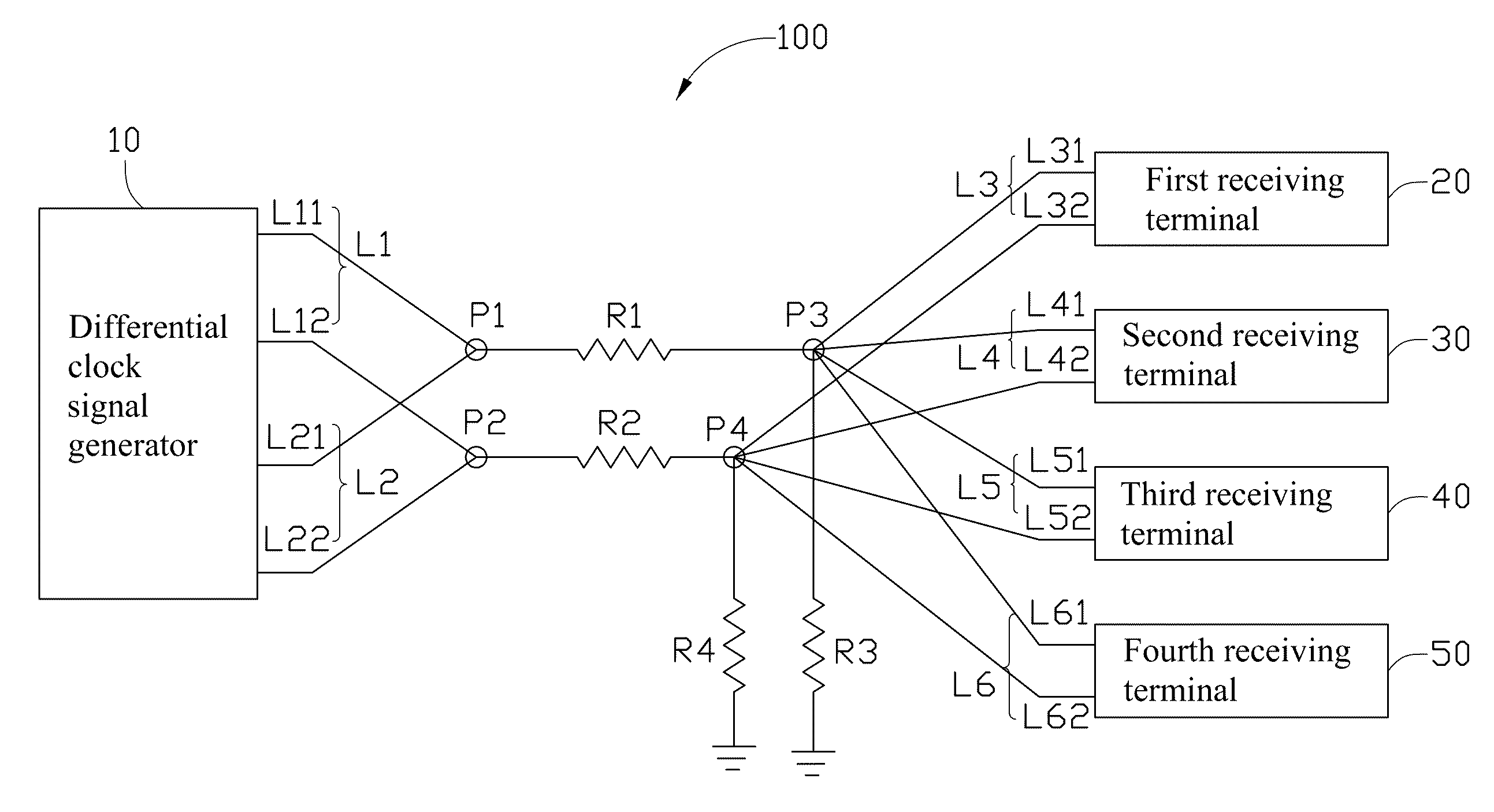
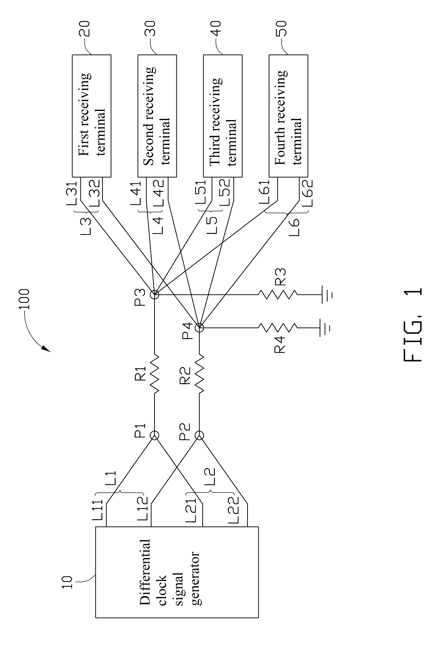
[0007]Referring to FIG. 1, an exemplary embodiment of a differential signal transmission device 100 includes a differential clock signal generator 10, a first receiving terminal 20, a second receiving terminal 30, a third receiving terminal 40, a fourth receiving terminal 50, two matching resistors R1 and R2, and two grounding resistors R3 and R4. The differential signal transmission device 100 may be formed on a printed circuit board.

[0008]The differential clock signal generator 10 provides two differential clock signal pairs L1 and L2. The differential clock signal pair L1 includes a positive signal L11 and a negative signal L12. The differential clock signal pair L2 includes a positive signal L21 and a negative signal L22. The positive signals L11 and L21 are clustered at a first positive clustering point P1. The negative signals L12 and L22 are clustered at a first negative clustering point P2.

[0009]The first positive clustering point P1 is connected to a second positive cluster...


PUM


Abstract

A differential signal transmission device transmits N differential signal pairs from a differential signal generator to a number of receiving terminals. The N differential signal pairs include N positive signals and N negative signals. The N positive signals are clustered at a first positive clustering point. The first positive clustering point is connected to a second positive clustering point via a first matching resistor. The second positive clustering point is grounded via a first grounding resistor, and outputs a number of positive signals to the number of receiving terminals respectively. The N negative signals are clustered at a first negative clustering point. The first negative clustering point is connected to a second negative clustering point via a second matching resistor. The second negative signal clustering point is grounded via a second grounding resistor, and outputs a number of negative signals to the number of receiving terminals respectively.

Description

BACKGROUND[0001]1. Technical Field[0002]The present disclosure relates to differential signal transmission devices, and particularly to a differential clock signal transmission device.[0003]2. Description of Related Art[0004]Clock signals are significant for an electronic device to synchronously activate components in the electronic device. A number of differential clock signal pairs from a differential clock signal generator should be equal to a number of receiving terminals when the differential clock signal pairs are transmitted by a common signal transmission device. For example, the differential clock signal generator just can provide two differential clock signal pairs to two receiving terminals. If the number of the receiving terminals is more than two, voltages at the receiving terminals may be too low and thereby unsatisfied to a required specification. Additionally, each of the receiving terminals should be grounded via a resistor when the differential clock signal pairs a...

Claims


Application Information

Patent Timeline
Patent Type & Authority Patents(United States)
IPC IPC(8): H03H7/38
CPCH04L25/0272
Inventor HSU, SHOU-KUOLEE, CHENG-HSIENLAI, YING-TSOSU, HSIAO-YUNCHEN, JIA-CHI
Owner HON HAI PRECISION IND CO LTD
Learn More