Optical lens assembly

a technology of optical lens and lens assembly, which is applied in the field of optical lens assembly, can solve the problems of excessive sensitivity of the positive second lens element, insufficient three-element lens assembly for a high-end imaging lens module, and long total track length, so as to achieve the effect of reducing the size of the optical lens assembly, improving the sensitivity of the optical system, and improving the resolution

Active Publication Date: 2012-10-09
LARGAN PRECISION
View PDF3 Cites 21 Cited by
  • Summary
  • Abstract
  • Description
  • Claims
  • Application Information

AI Technical Summary

Benefits of technology

[0010]With the aforementioned arrangement of lens elements, the size of the optical lens assembly can be effectively reduced, the sensitivity of the optical system can be attenuated, and the resolution can be increased. Additionally, the lens elements employed in a conventional imaging lens assembly and those used in an infrared optical system are made of different materials. Take an infrared optical system for example, the lens elements used therein are generally made of germanium (Ge) or other materials (such as ZnSe, ZnS, etc.). The present optical lens assembly is not only characterized by better image quality, but is capable of being integrated into the infrared optical system for image formation. Therefore, the present invention has a wider range of applications than a general imaging lens assembly.
[0011]In the present optical lens assembly, the first lens element with positive refractive power provides part of the refractive power for the optical system so that the total track length of the optical lens assembly can be favorably reduced; the second lens element has positive refractive power so that the refractive power of the first lens element can be favorably distributed and thereby to attenuate the sensitivity of the optical system; the third lens element has negative refractive power so that the aberration caused by the positive refractive power of the optical system and the chromatic aberration can be favorably corrected; the fourth lens element has positive refractive power so that the high order aberrations of the optical system can be favorably corrected, thereby increasing the resolution of the optical lens assembly.
[0012]Moreover, each of the third lens element and the fourth lens element may be provided with at least one inflection point, thereby the angle at which the light is projected onto the sensor from the off-axis field can be effectively reduced to further correct the off-axis aberrations.

Problems solved by technology

Therefore, the three-element lens assembly has become insufficient for a high-end imaging lens module, such as camera units on current high-end smartphones.
Such arrangement of optical elements, however, will results in a longer total track length as well as the sensitivity of the positive second lens element remains excessively high.

Method used


Image

  • Optical lens assembly
  • Optical lens assembly
  • Optical lens assembly

Examples


first embodiment

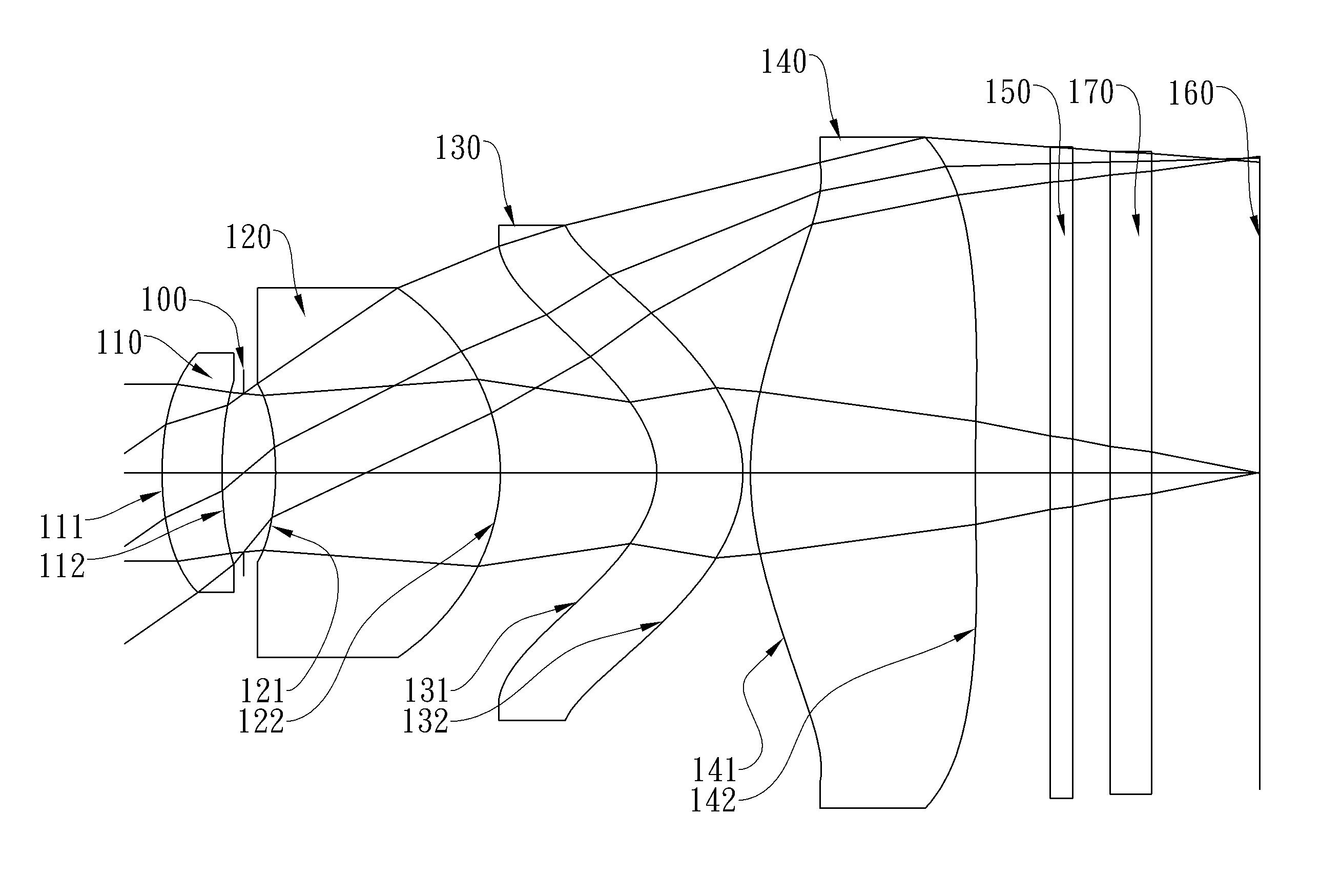
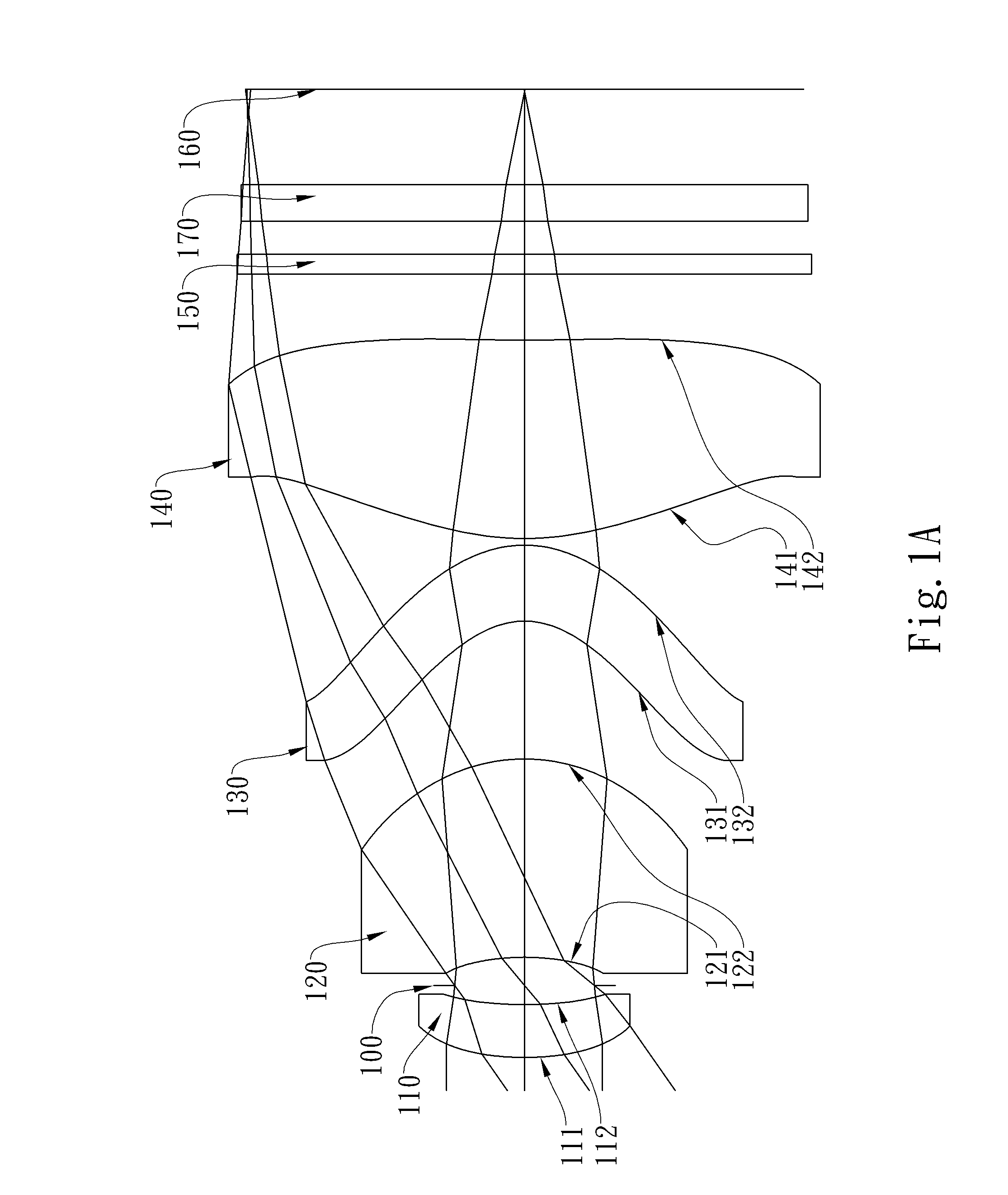
[0067]In the present optical lens assembly, the vertical distance between the farthest point of the effective light entry area on the image-side surface of the fourth lens element and the optical axis is Y42; the distance on the optical axis between the image-side surface of the fourth lens element and the vertical projection from the farthest point on the image-side surface of the fourth lens element to the optical axis is SAG42. The distances and relative locations represented by Y42 and SAG42 will be further illustrated in FIG. 20. FIG. 20 is an enlarged view of the fourth lens element 140 of the present invention. The vertical distance between the farthest point 2001 of the effective light entry area on the image-side surface 142 of the fourth lens element 140 and the optical axis is Y42; the distance on the optical axis between the intersection 2002 of the image-side surface 142 of the fourth lens element 140 and the vertical projection of the farthest point 2001 on the image-s...

second embodiment

[0093]In the present optical lens assembly, the focal length of the optical lens assembly is f, and it satisfies the relation: f=5.88 (mm).

[0094]In the second embodiment of the present optical lens assembly, the f-number of the optical lens assembly is Fno, and it satisfies the relation: Fno=2.80.

[0095]In the second embodiment of the present optical lens assembly, half of the maximal field of view of the optical lens assembly is HFOV, and it satisfies the relation: HFOV=31.0 deg.

[0096]In the second embodiment of the present optical lens assembly, the thickness of the first lens element 210 on the optical axis is CT1, the thickness of the second lens element 220 on the optical axis is CT2, and they satisfy the relation: CT1 / CT2=0.26.

[0097]In the second embodiment of the present optical lens assembly, the thickness of the fourth lens element 240 on the optical axis is CT4, the focal length of the optical lens assembly is f, and they satisfy the relation: CT4 / f=0.47.

[0098]In the second...

third embodiment

[0109]In the present optical lens assembly, the focal length of the optical lens assembly is f, and it satisfies the relation: f=5.99 (mm).

[0110]In the third embodiment of the present optical lens assembly, the f-number of the optical lens assembly is Fno, and it satisfies the relation: Fno=2.80.

[0111]In the third embodiment of the present optical lens assembly, half of the maximal field of view of the optical lens assembly is HFOV, and it satisfies the relation: HFOV=31.0 deg.

[0112]In the third embodiment of the present optical lens assembly, the thickness of the first lens element 310 on the optical axis is CT1, the thickness of the second lens element 320 on the optical axis is CT2, and they satisfy the relation: CT1 / CT2=0.27.

[0113]In the third embodiment of the present optical lens assembly, the thickness of the fourth lens element 340 on the optical axis is CT4, the focal length of the optical lens assembly is f, and they satisfy the relation: CT4 / f=0.33.

[0114]In the third embo...


PUM


Abstract

This invention provides an optical lens assembly comprising, in order from an object side to an image side: a first lens element with positive refractive power; a second lens element with positive refractive power; a third lens element with negative refractive power having a concave object-side surface and a convex image-side surface, at least one of the object-side and image-side surfaces thereof being aspheric; and a fourth lens element with positive refractive power having an aspheric object-side surface and an aspheric image-side surface; wherein the number of lens elements with refractive power is four.

Description

CROSS-REFERENCE TO RELATED APPLICATIONS[0001]This non-provisional application claims priority under 35 U.S.C. §119(a) on Patent Application No(s). 099136447 filed in Taiwan, R.O.C. on Oct. 26, 2010, the entire contents of which are hereby incorporated by reference.BACKGROUND OF THE INVENTION[0002]1. Field of the Invention[0003]The present invention relates to an optical lens assembly, and more particularly, to a compact optical lens assembly applicable to electronic products.[0004]2. Description of the Prior Art[0005]The demand for compact imaging lens assemblies has grown in recent years as the popularity of portable electronic products with the photographing function has increased, and the sensor of a general photographing camera is none other than CCD (Charge Coupled Device) or CMOS (Complementary Metal-Oxide Semiconductor Sensor). Furthermore, as advances in manufacturing technology of semiconductor have allowed the pixel size of sensors to be reduced, and the resolution of comp...

Claims


Application Information

Patent Timeline
Patent Type & Authority Patents(United States)
IPC IPC(8): G02B9/34G02B13/18
CPCG02B13/004G02B9/34
Inventor HSU, CHIH WENHUANG, HSIN HSUAN
Owner LARGAN PRECISION
Why Eureka
Try Eureka