
Head gimbal assembly and information recording apparatus

a technology of information recording apparatus and gimbal, which is applied in the direction of recording information storage, instruments, and support for heads, can solve the problems of difficult control of sliders by actuators and unstable flying of sliders, and achieve stable flying of sliders, reduced stress that is transmitted from the waveguide, and improved accuracy

Inactive Publication Date: 2012-10-09
HITACHI LTD
View PDF14 Cites 33 Cited by
  • Summary
  • Abstract
  • Description
  • Claims
  • Application Information

AI Technical Summary

Benefits of technology

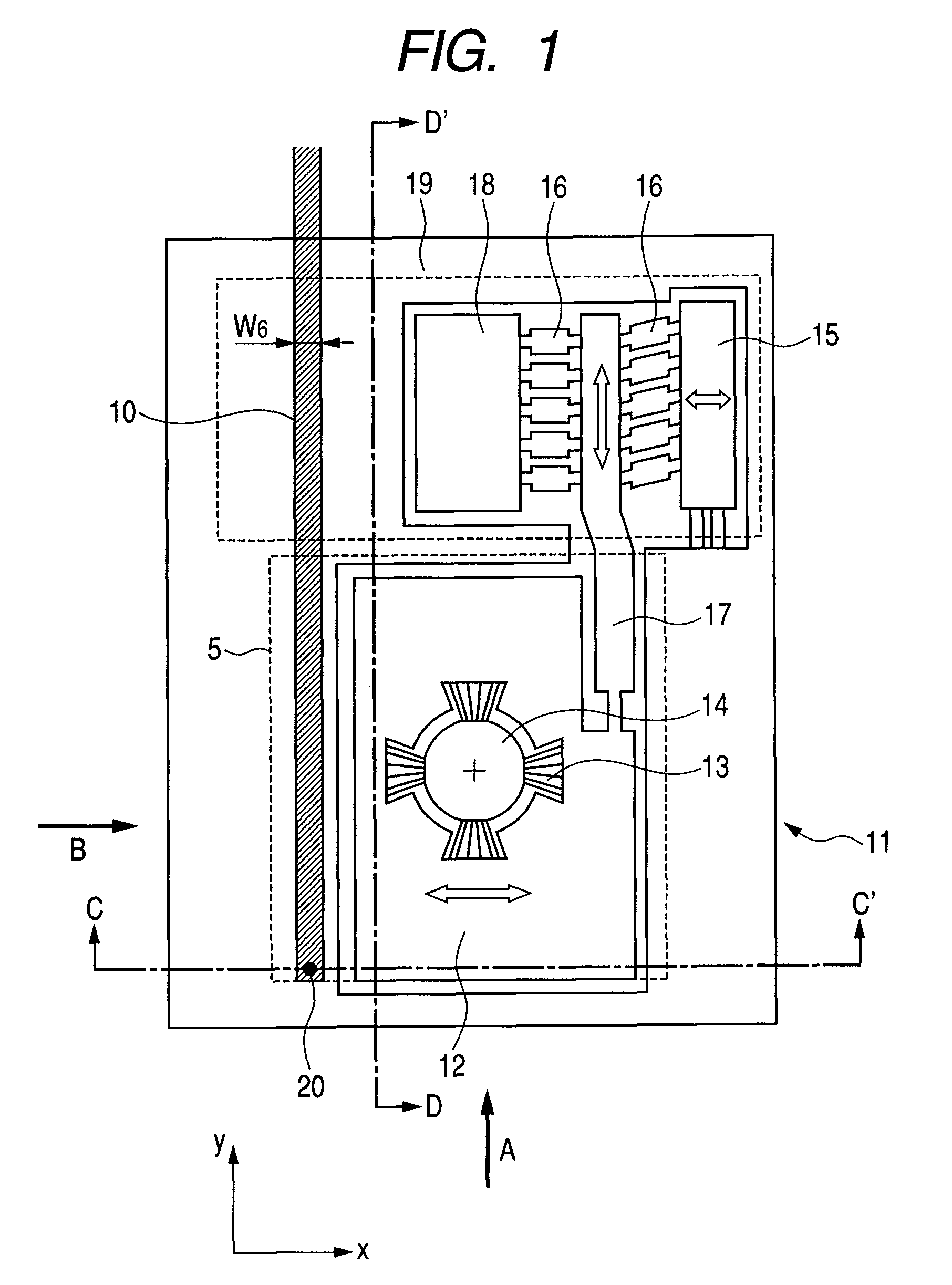
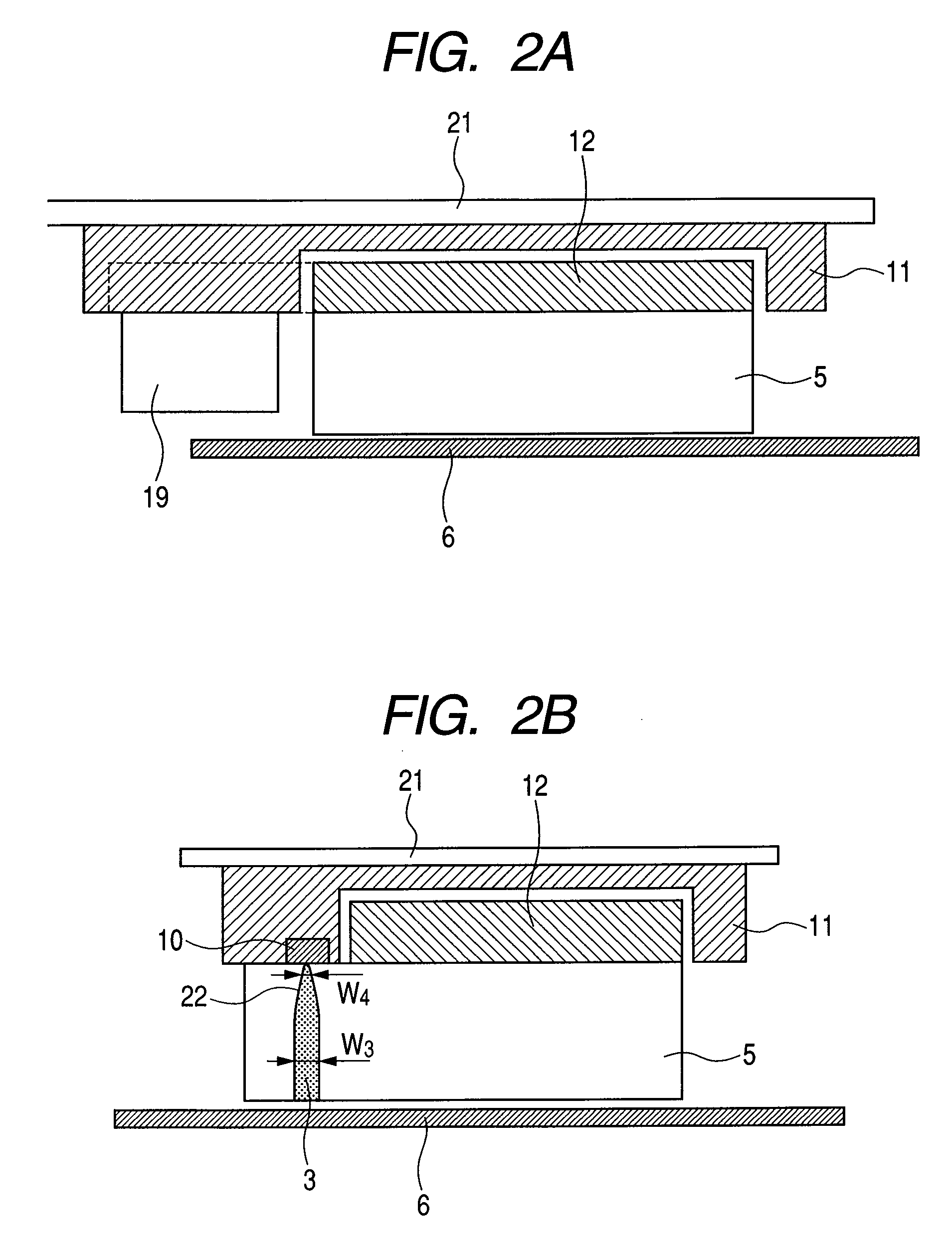
[0008]A head gimbal assembly according to the present invention includes a flying slider, a suspension, and a mount, wherein the mount includes a movable portion to which the flying slider is fixed, a piezo element that is fixed to the suspension and is used for adjusting a position of the flying slider, and a fixed portion to which the waveguide for optical transmission is mounted. A mirror is formed at the end portion of the waveguide on the fixed portion, such that a light emitted from the waveguide is directly coupled in the waveguide formed inside the flying slider. The waveguides on the movable portion side and the fixed portion side are not in contact with each other, but structured such that the waveguide on the movable portion side is movable relative to that on the fixed portion side. Accordingly, a stress is never transmitted from the waveguide on the fixed portion side to the movable portion. Due to this, the flying stability of the flying slider, which is fixed to the movable portion, is not impaired by a stress from the waveguide. It is also possible that the movable portion can be moved actively by the piezo element or the like.
[0014]An intensity of the light source may also be adjusted by detecting an intensity of a light that is coupled in the waveguide inside the slider, then by forming a feedback loop based on the detected intensity. That is, when the detected light intensity is large, an intensity of the light source (or an input current amount) is made small, and in the opposite case, an intensity of the light source is made large, thereby the intensity fluctuation can be suppressed.
[0016]The movable portion for the tracking servo may also be provided inside the slider. Due to the structure, the movable portion can be lighter, thereby the movable portion can moves at a higher response speed.
[0017]An optical device, such as a lens, may also be inserted between the waveguide for propagating a light from the light source, and the waveguide inside the slider. For example, lenses are arranged at the emitting portion of the waveguide for propagating a light from the light source (on the fixed portion side), and at the incident portion of the waveguide inside the slider (on the movable portion side), respectively, such that a light propagates between the two lenses as a parallel light. When a light propagates as a parallel light in such a manner, the distance between the focal point of the lens and the end portion of the waveguide is not changed, even when the movable portion moves; thereby, a fluctuation of the coupling efficiency between the two waveguides can be suppressed when the movable portion moves. It is noted that, in this case, assuming that the focal distance of the lens and a mode field diameter on the side of the waveguide for propagating a light from the source light, are f1 and d1, respectively; and the focal distance of the lens and a mode field diameter, on the side of the waveguide inside the slider, f2 and d2, respectively, the coupling efficiency between the two waveguides can be a maximum when f1 / f2=d1 / d2 is satisfied. In the case, by satisfying f1>f2, positions of the waveguide can be easily controlled at the coupling potion between the light source and the waveguide for optical transmission (the larger a mode field diameter, the larger a tolerance for the dislocation).
[0019]According to the present invention, in a thermally assisted magnetic recording apparatus in which a semiconductor laser, which is a light source, is arranged outside a flying slider, and the semiconductor laser and the flying slider are connected by a waveguide, a stress that is transmitted from the waveguide to the flying slider can be reduced, thereby allowing the stable flying of the slider to be achieved. Also, an actuator can be arranged near the flying slider, thereby allowing the tracking with a higher accuracy to be achieved.

Problems solved by technology

When a light is guided from a semiconductor laser to a flying slider through a waveguide, a stress of the waveguide is transmitted to the flying slider, resulting in the unstable flying of the slider.
However, when the light waveguide is coupled to the flying slider, the slider is hindered in its movement, thereby resulting in the fact that the slider is difficult to be controlled by the actuator.

Method used


Image

  • Head gimbal assembly and information recording apparatus
  • Head gimbal assembly and information recording apparatus
  • Head gimbal assembly and information recording apparatus

Examples


Embodiment Construction

[0047]Hereinafter, embodiments according to the present invention will be described with reference to the accompanying drawings.

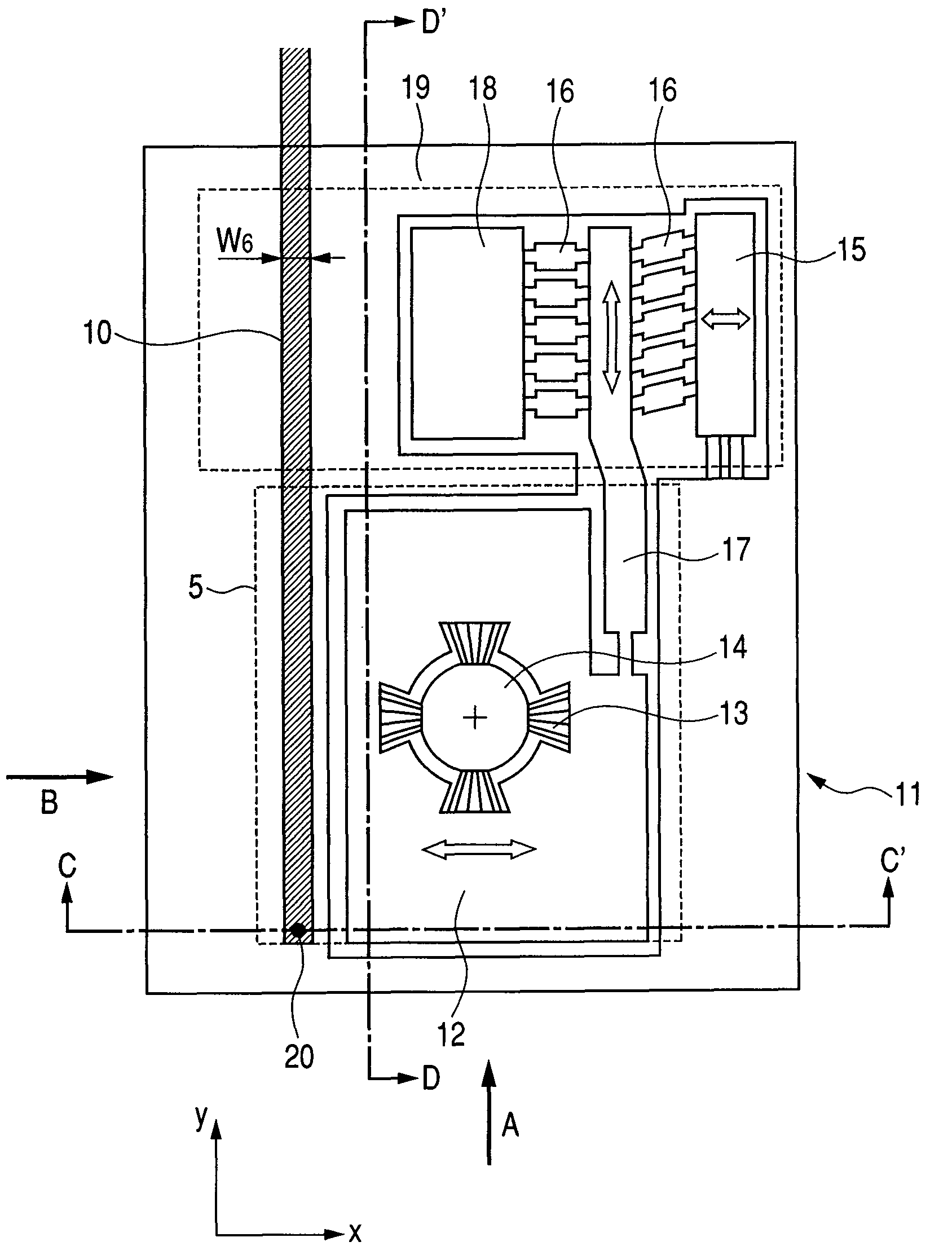
[0048]FIGS. 1 to 3 illustrate a structure example of the case where the waveguide and the slider are formed on the mount having a mechanism for adjusting positions of the slider for the tracking servo. FIG. 1 illustrates a view of the bottom face of the mount(seen from the media side); FIG. 2A a cross-sectional side view taken along line “D-D′”, seen from the direction of the arrow B in FIG. 1; FIG. 2B a cross-sectional side view taken along line “C-C′”, seen from the direction of the arrow A in FIG. 1; and FIG. 3 a cross-sectional side view of the head and a medium seen from the direction of the arrow B. The present structure is composed of the flying slider 5, the suspension 21, and the mount. The mount is composed of the fixed portion 11, the movable portion 12 to which the flying slider 5 is fixed (slider holding portion), the piezo element 19 for adjus...


PUM

PropertyMeasurementUnit
mode field diameteraaaaaaaaaa
mode field diametersaaaaaaaaaa
thicknessaaaaaaaaaa

Abstract

When a semiconductor laser is arranged outside a slider and a light is to be guided to the slider through a waveguide, the following problems will be solved: the stability of the flying slider is deteriorated due to a stress from the waveguide; and when an actuator is arranged near the flying slider, the motions of the slider are hindered by the waveguide. A waveguide for guiding a light to a light irradiating unit inside a slider, which floats over a medium and has the light irradiating unit for irradiating a light to the medium; and a waveguide for propagating a light from the light source to the waveguide inside the slider, are included. The two waveguides are not in contact with each other, and a relative portion between the two waveguides is movable.

Description

CLAIM OF PRIORITY[0001]The present application claims priority from Japanese patent application JP 2008-009202 filed on Jan. 18, 2008, the content of which is hereby incorporated by reference into this application.FIELD OF THE INVENTION[0002]The present invention relates to a head gimbal assembly having a flying slider that irradiates a light to a recording medium, and to an information recording apparatus provided with the same.BACKGROUND OF THE INVENTION[0003]In recent years, a thermally assisted magnetic recording has been proposed as a means of realizing high recording density of 1 Tb / in2 or more (H. Saga, H. Nemoto, H. Sukeda, and M. Takahashi, Jpn. J. Appl. Phys. 38, Part 1, and pp. 1839 (1999)). In conventional magnetic recording apparatuses, when a recording density is 1 Tb / in2 or more, there is a problem that recorded information is lost due to a heat fluctuation. In order to prevent this, it is necessary to increase a coercivity of a magnetic recording medium; however, the...

Claims


Application Information

Patent Timeline
Patent Type & Authority Patents(United States)
IPC IPC(8): G11B11/00
CPCG11B5/4826G11B5/4866G11B5/4873G11B2005/0021G11B5/6088
Inventor MATSUMOTO, TAKUYA
Owner HITACHI LTD
Learn More