
Wall-lifting systems

a technology of lifting system and framed wall, which is applied in the field of improved wall lifting system, can solve the problems of collapse back onto workers located under the structure, manual lifting of framed wall can become too heavy and unstable for lifting personnel, and the framed wall is large and unwieldy

Inactive Publication Date: 2012-10-16
VAN ROEKEL CHAD A
View PDF17 Cites 7 Cited by
  • Summary
  • Abstract
  • Description
  • Claims
  • Application Information

AI Technical Summary

Benefits of technology

[0007]It is a further object and feature of the present invention to provide such a system that permits safe lifting of walls during framing and building processes.
[0008]Another object and feature of the present invention is to provide savings to builders and owners of the built structures.
[0009]Other objects and features of the present invention are to allow quicker finish times, fewer job-site accidents, and less material damage.
[0010]A further object and feature of the present invention is to decrease insurance claims and costs, by lessening the likelihood that workers are injured during building construction.
[0011]A further object and feature of the present invention is to increase project bidding reliability, leading to greater client satisfaction with fewer cost and time-overruns.
[0012]Yet another object and feature of the present invention is to provide a greater means of efficiency and cost-effectiveness within the building industry.

Problems solved by technology

Framed walls tend to be large and unwieldy requiring a large work crew to manually lift the framing into place.
Manually raised framed walls can become too heavy and unstable for the lifting personnel and can collapse back onto workers located under the structure.
This problem is often compounded when raising large multi-story wall sections (balloon framing), due to the increased weight and height of the sections.
In the United States, the Occupational Safety and Health Administration (OSHA) has documented numerous injuries related to accidents occurring during the lifting of framed walls, including injuries that resulted in death.
As the popularity of light-framed construction increased, framing contractors developed a variety of rudimentary techniques for the manual lifting of such walls; however, these improvised techniques are often of marginal safety benefit and frequently rely heavily on a construction foreman guessing the weight of a wall and estimating the number of workers necessary to perform the lift.
Many lifting failures can be attributed to insufficient numbers of lifting personnel resulting in inadequate support during the lift.

Method used


Image

  • Wall-lifting systems
  • Wall-lifting systems
  • Wall-lifting systems

Examples


Embodiment Construction

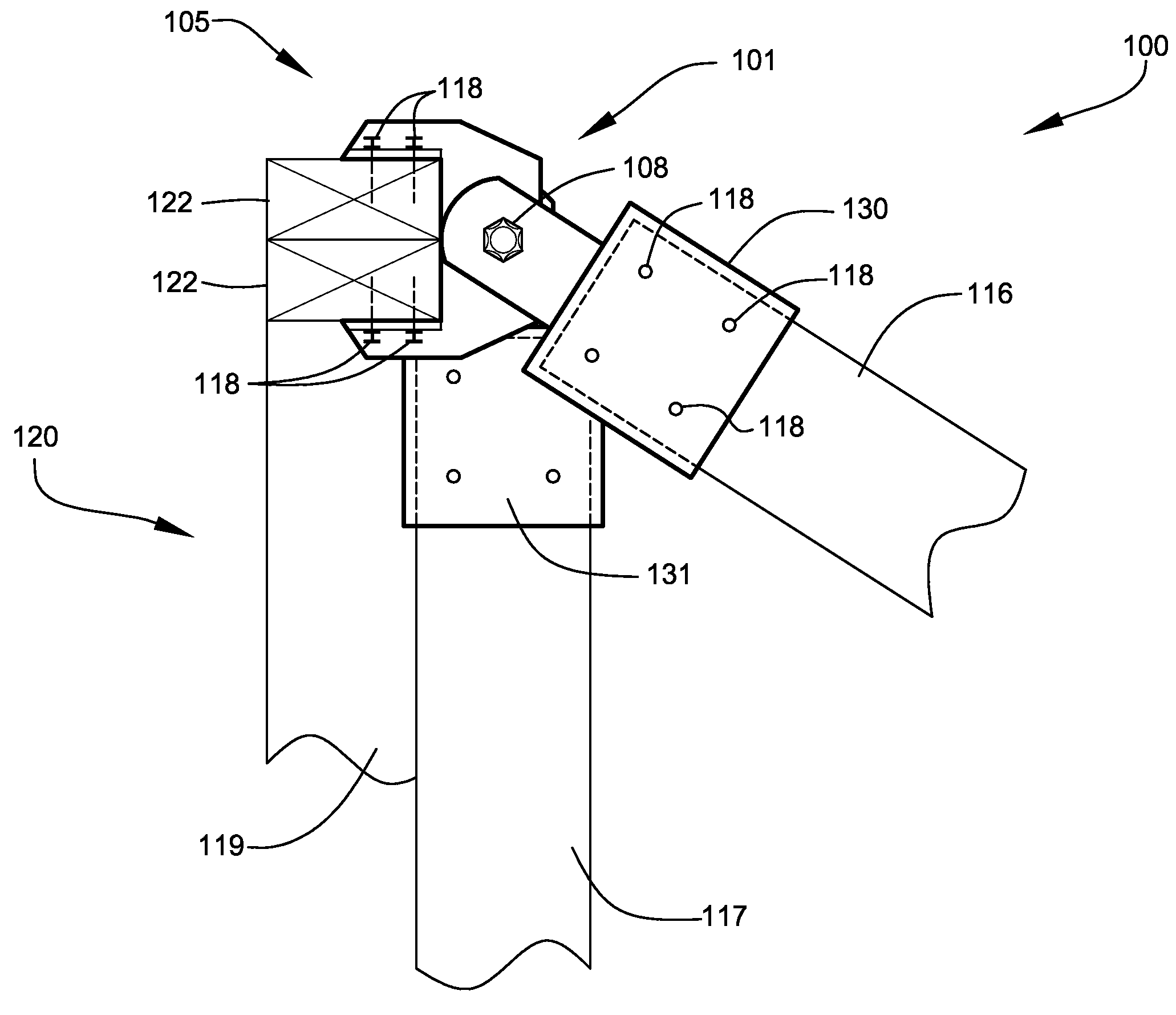
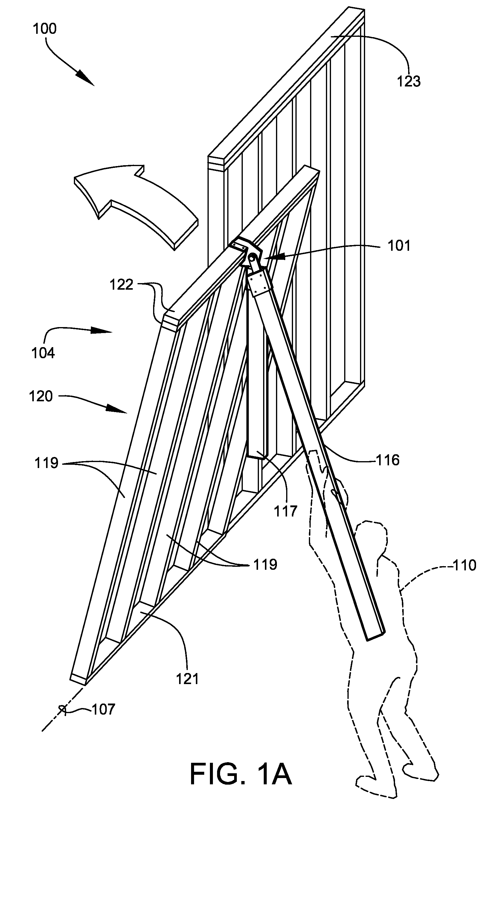
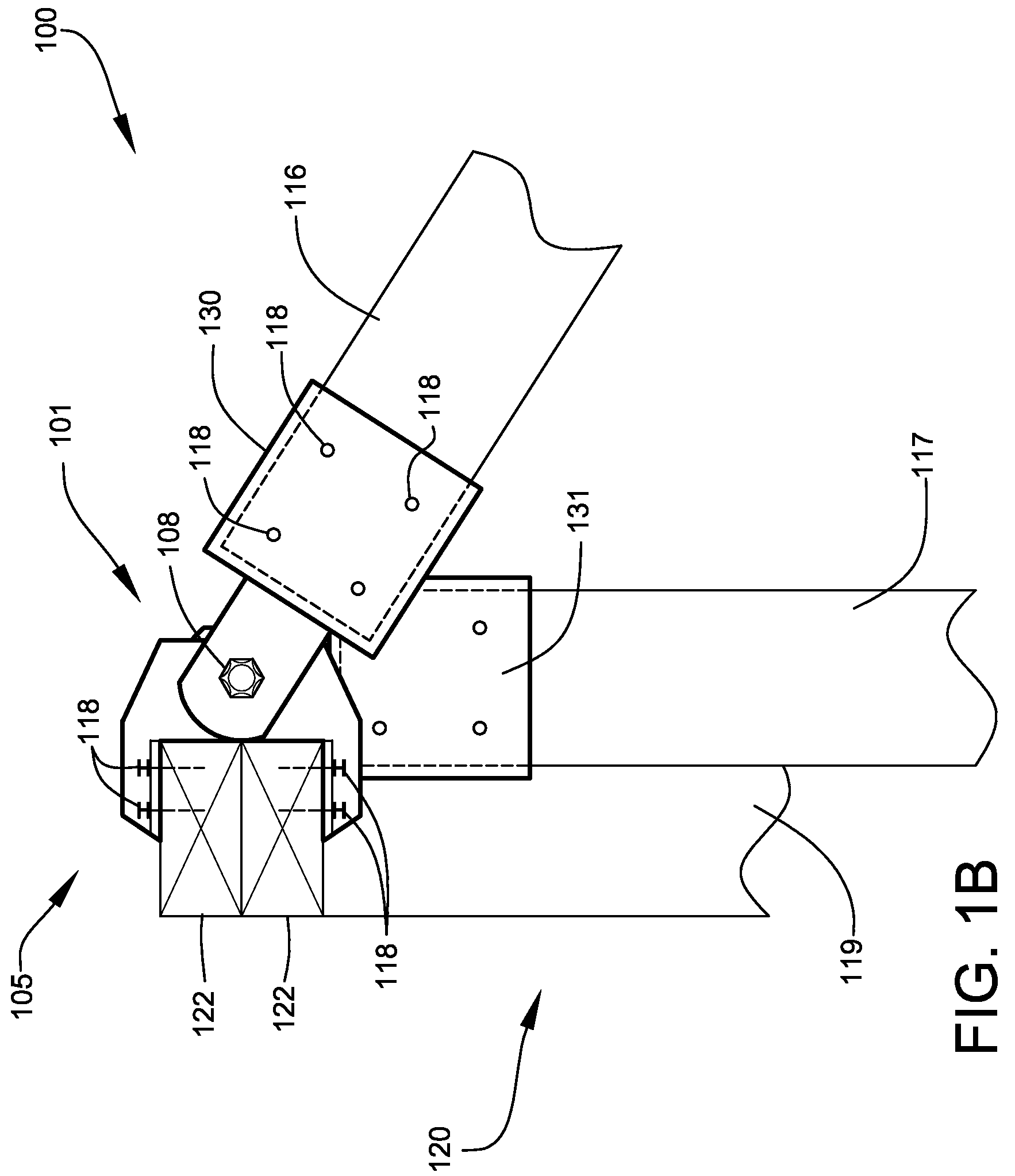
[0033]Light-frame building construction is generally accomplished by the joining together of a plurality of partially assembled framed walls that are initially constructed horizontally and raised into their final vertical position. FIG. 1A shows a perspective view, illustrating wall-lifting system 100 engaged on wall framing 120 to assist in lifting the assembly from a substantially horizontal position to a substantially vertical position, according to a preferred embodiment of the present invention. Wall framing 120 is preferably constructed by assembling a plurality of structural studs 119, spaced at regular intervals between a pair of top plates 122 and at least one bottom plate 121 (also referred to as a sole plate), as shown. Studs 119, top plates 122, and bottom plate 121 are preferably formed from standardized dimensional wood lumber. Studs 119 may alternately comprise light-gauge steel members with upper and lower receiving tracks substituted for the top and bottom plates. S...


PUM


Abstract

A system for safe, efficient lifting of partially fabricated walls during light-frame construction. Such walls are built in a horizontal position and are manually rotated into a vertical position using a lifting apparatus mounted to one or more framing members of the wall. The lifting apparatus allows the wall to be positioned and held at an intermediate resting / safety point for protection of user during the lift. A method of use and kit comprising the lifting apparatus are also disclosed.

Description

CROSS-REFERENCE TO RELATED APPLICATION[0001]The present application is related to and claims priority from prior provisional application Ser. No. 61 / 090,198, filed Aug. 19, 2008, entitled “WALL-LIFTING SYSTEMS”, the content of which is incorporated herein by this reference and is not admitted to be prior art with respect to the present invention by the mention in this cross-reference section.BACKGROUND[0002]This invention relates to improved wall lifting systems used during the construction of framed structures. More particularly, this invention relates to providing a system for safe, efficient lifting of partially fabricated walls during light-frame construction.[0003]In typical light-frame construction, walls are partially fabricated in a horizontal position, typically at ground level, and are subsequently raised to a vertical position during assembly of the wall. Framed walls tend to be large and unwieldy requiring a large work crew to manually lift the framing into place. Manual...

Claims


Application Information

Patent Timeline
Patent Type & Authority Patents(United States)
IPC IPC(8): B66F3/00E04G21/16
CPCE04G21/168
Inventor VAN ROEKEL, CHAD A.
Owner VAN ROEKEL CHAD A
Learn More