One touch pivoting expandable power and data center

a data center and one-touch technology, applied in the direction of live contact access prevention, electrical equipment, coupling device connections, etc., can solve the problems of entanglement of electrical cords and communications wires connected to devices, the positioning of electrical power outlets and communication ports, and the rapid increase in electrical materials

Active Publication Date: 2012-10-16
BYRNE NORMAN R
View PDF12 Cites 35 Cited by
  • Summary
  • Abstract
  • Description
  • Claims
  • Application Information

AI Technical Summary

Problems solved by technology

Historically, one problem common to the use of electrical power and communications equipment is the positioning of electrical power outlets and communication ports, such as conventional RS-232 voice / data interface connectors.
However, the cost of electrical materials rapidly increases as the number of power source receptacles and associated equipment is increased.
In addition, and perhaps more importantly, the conventional design of single- or double-unit receptacles (for both electrical power and communications) within walls or floor surfaces, which are often a substantial distance from the devices to be powered or with which to communicate, cause unsightly and sometimes dangerous arrays, and may result in entanglements of the electrical cords and communications wires connected to the devices.
Again, however, the raceways can result in unsightly and entangled arrays of electrical cords and communication lines.
In addition, such raceways are often located on floor surfaces and are not particularly convenient.
Accordingly, these receptacles and communication ports are typically in a fairly “open” location, and the device cords again may prove to be unsightly and space consuming.
If, alternatively, the receptacles and communication ports are somewhat hidden from view, they can be difficult to access.
That is, the use of springs or similar arrangements can sometimes result in additional repair and maintenance costs.
Further, the use of a relatively long extrusion and spring assemblies can also result in higher initial costs.

Method used


Image

  • One touch pivoting expandable power and data center
  • One touch pivoting expandable power and data center
  • One touch pivoting expandable power and data center

Examples


Embodiment Construction

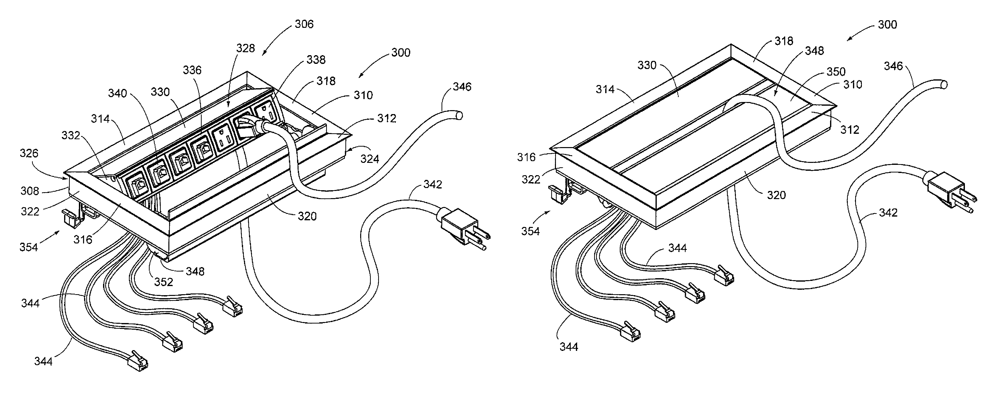
[0098]The principles of the invention are disclosed, by way of example, in an expandable and pivotable power and data center shown in four embodiments of expandable power and data centers as illustrated in FIGS. 18-62. More specifically, certain of FIGS. 18-62 illustrate an embodiment referred to herein as an expandable power and data center 300. Others of the drawings of FIGS. 18-51 illustrate a second embodiment of a power data center in accordance with the invention, referred to as an expandable power and data center 600. Also, expandable power and data centers 700 and 800 are illustrated in FIGS. 61 and 62 respectively. The expandable power and data centers 300, 600, 700 and 800 in accordance with the invention provide several advantages over known assemblies. Expandable power and data centers in accordance with the invention are adapted to support variable numbers of electrical devices (such as power receptacles) and various numbers of communication devices (such as data ports)...


PUM


Abstract

An expandable power and data center (300) is adapted to be mounted within a slot (304) of a work surface (302). The power and data center (300) includes a stationary housing (306) and a carriage (328). The carriage (328) includes socket areas where power receptacles (338) and data ports (340) can be inserted. A top surface (330) of the carriage (328) and a top surface (350) of a frontal cover (348) form a pressure area (360). With the carriage in a closed position (328), a user can exert a downward pressure on the pressure area (360), causing the carriage (328) to move to an open position. A damper (368) restricts the speed at which the carriage (328) moves between the closed position and an open position.

Description

CROSS-REFERENCE TO RELATED APPLICATIONS[0001]This application is based on and claims priority of U.S. Utility patent application Ser. No. 11 / 917,258 filed Dec. 12, 2007, based on an international filing of International Patent Application Serial No. PCT / US06 / 22952 filed Jun. 13, 2006, which is based on and claims priority of U.S. Provisional Patent Application Ser. No. 60 / 690,009, filed Jun. 13, 2005.STATEMENT REGARDING FEDERALLY SPONSORED RESEARCH OR DEVELOPMENT[0002]Not applicable.REFERENCE TO A MICROFICHE APPENDIX[0003]Not applicable.FIELD OF THE INVENTION[0004]The invention relates to electrical power, and power and data distribution systems and, more particularly, to power and data center systems having capabilities of expansion and pivoting between open and closed positions.DESCRIPTION OF RELATED ART[0005]The use of computers, sophisticated telecommunications equipment and other electronic devices is continuing to rapidly increase in commercial, industrial and other office env...

Claims


Application Information

Patent Timeline
Patent Type & Authority Patents(United States)
IPC IPC(8): H01R13/44
CPCH01R27/02H02G3/185
Inventor BYRNE, NORMAN R.
Owner BYRNE NORMAN R
Why Eureka
Try Eureka