
Vehicular control apparatus and vehicular control method

a technology of vehicular control and control apparatus, which is applied in the direction of mechanical apparatus, digital data processing details, instruments, etc., can solve the problems of engine speed, engine input rotation speed, engine output torque drop, etc., and achieve the effect of reducing the output torque of the internal combustion engine and reducing the learning frequency

Active Publication Date: 2012-10-16
TOYOTA JIDOSHA KK
View PDF16 Cites 6 Cited by
  • Summary
  • Abstract
  • Description
  • Claims
  • Application Information

AI Technical Summary

Benefits of technology

[0015]This invention thus provides a vehicle control apparatus and a vehicle control method, which can prevent erroneous learning of a hydraulic pressure command value used when increasing hydraulic pressure applied to an apply element in order to apply that apply element so as to shift an automatic transmission into a higher gear.
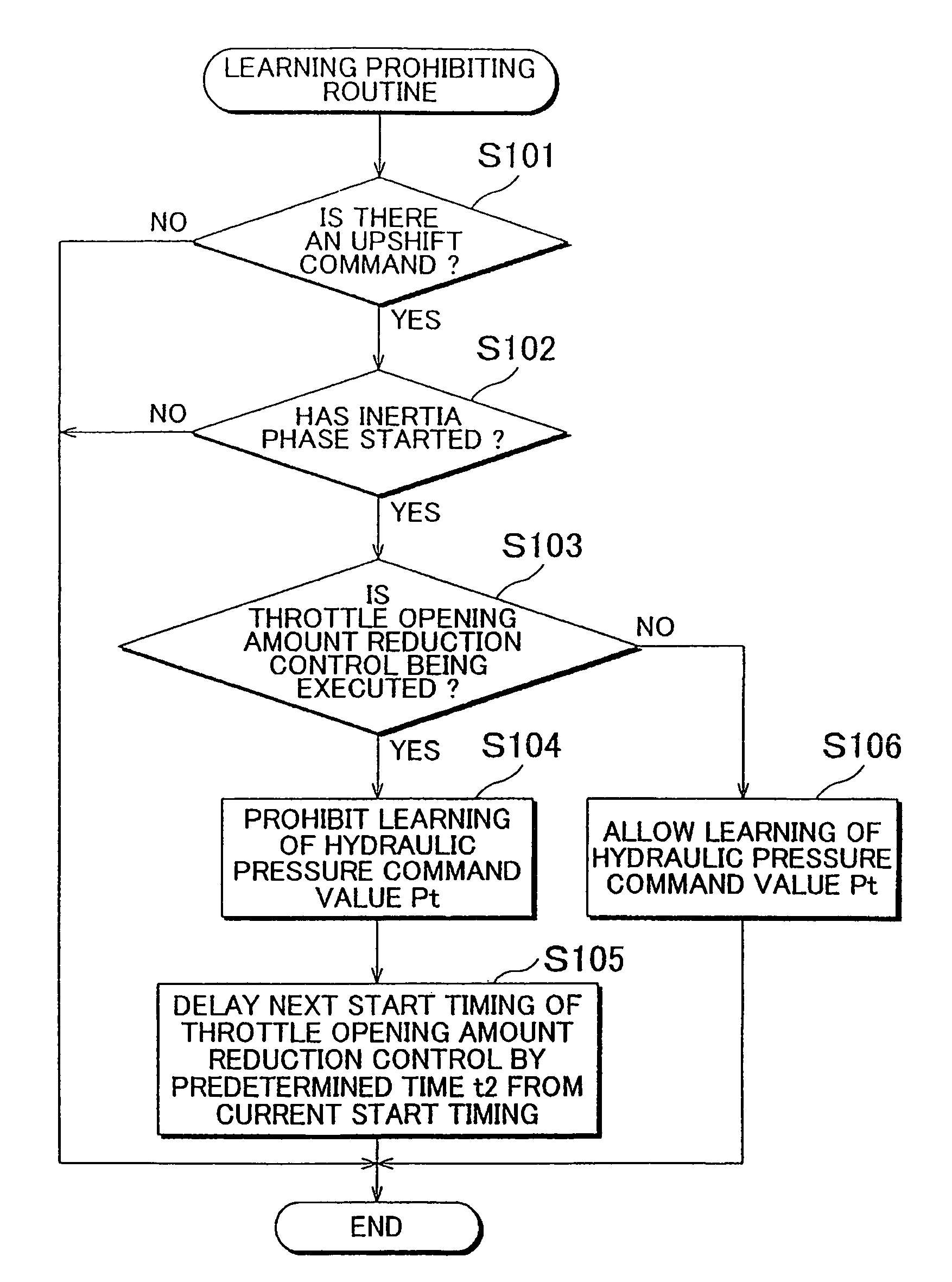
[0018]The determination that the inertia phase, which occurs when the second apply element is applied in order to shift the automatic transmission into a higher gear, has started is made based on the fact that the input rotation speed of the automatic transmission has started to decrease. Here, if the control to decrease the throttle opening amount is being performed when it is determined that the inertia phase has started, it is highly likely that that determination is erroneous because the control to decrease the throttle opening amount causes the output torque of the internal combustion engine to drop which in turn reduces the input rotation speed of the automatic transmission (i.e., the engine speed). If the hydraulic pressure command value used when increasing the hydraulic pressure applied to the second apply element to apply that apply element is learned when it is highly likely that the determination that the inertia phase has started is erroneous in this way, the learned hydraulic pressure command value may be erroneous. However, according to the foregoing vehicular control apparatus and vehicular control method, learning of the hydraulic pressure command value is prohibited when the output torque from the internal combustion engine is being reduced through control by the torque reducing control which the opening amount of the throttle valve is reduced. As a result, the problem of erroneously learning the hydraulic pressure command value in this way can be avoided.
[0020]When the learning of the hydraulic pressure command value is prohibited it means that the start of the control to decrease the opening amount of the throttle valve to reduce the output torque of the internal combustion engine is too early. Therefore, according to the foregoing vehicular control apparatus and vehicular control method, when the learning of the hydraulic pressure command value is prohibited, the next start timing of the control to decrease the opening amount of the throttle valve is consequently delayed compared to the last start timing so the start timing of that control will not be too early. Therefore, the next time there is an opportunity to learn the hydraulic pressure command value, that learning can be inhibited from being prohibited to suppress a decrease in the learning frequency of the hydraulic pressure command value due to the learning of the hydraulic pressure command value being prohibited.

Problems solved by technology

Here, if the control to decrease the throttle opening amount is being performed when it is determined that the inertia phase has started, it is highly likely that that determination is erroneous because the control to decrease the throttle opening amount causes the output torque of the internal combustion engine to drop which in turn reduces the input rotation speed of the automatic transmission (i.e., the engine speed).
If the hydraulic pressure command value used when increasing the hydraulic pressure applied to the second apply element to apply that apply element is learned when it is highly likely that the determination that the inertia phase has started is erroneous in this way, the learned hydraulic pressure command value may be erroneous.

Method used


Image

  • Vehicular control apparatus and vehicular control method
  • Vehicular control apparatus and vehicular control method
  • Vehicular control apparatus and vehicular control method

Examples


Embodiment Construction

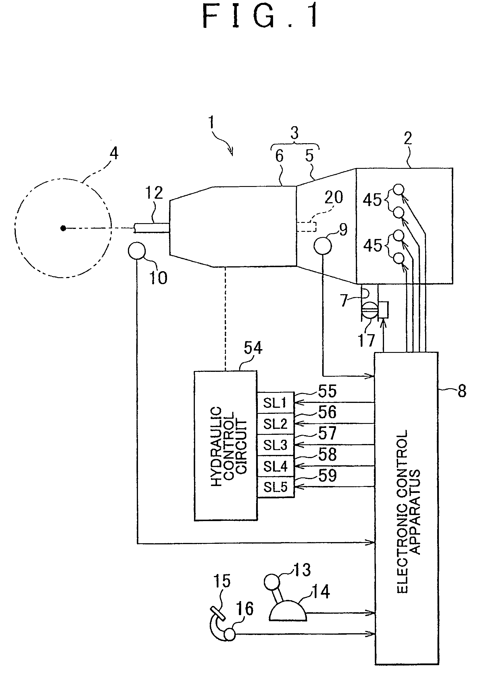
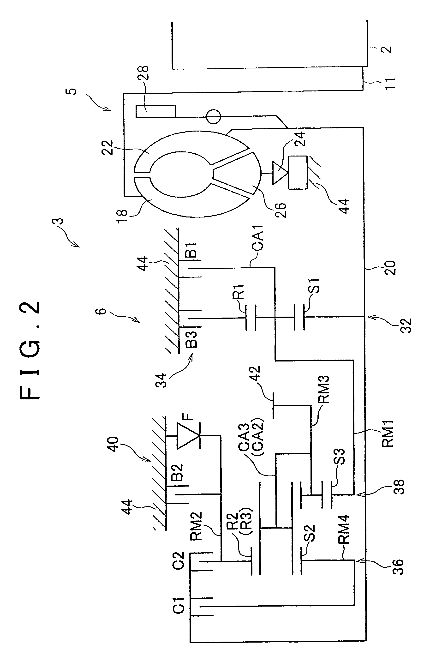
[0032]In the following description and the accompanying drawings, the present invention will be described in greater detail with reference to example embodiments. As shown in FIG. 1, in a vehicle 1, the rotation of an engine 2 is transmitted to wheels 4 via an automatic transmission 3 and the like. In the engine 2, the intake air amount is adjusted by adjusting the opening amount of a throttle valve 17 provided in an intake passage 7, and fuel of a quantity corresponding to that intake air amount is injected from a fuel injection valve 45. The intake air and the fuel mix to form an air-fuel mixture which is then combusted, and the power obtained from that combustion drives the engine 2. Also, the automatic transmission 3 includes a torque converter 5 and a gear shift mechanism 6, and establishes a plurality of gears with different gear ratios by selectively applying a plurality of apply elements such as clutches and brakes so as to switch the power transmitting path in the gear shif...


PUM


Abstract

When shifting an automatic transmission into a higher gear, it is determined that an inertia phase has started when an input rotation speed of the automatic transmission has started to decrease. Here, if throttle opening amount reduction control is being performed to reduce the output torque of the engine when it is determined that the inertia phase has started, it is highly likely that that determination is erroneous because that control causes the input rotation speed of the automatic transmission (i.e., the engine speed) to decrease. When it is highly likely that the determination that the inertia phase has started is erroneous in this way, learning of a hydraulic pressure command value is prohibited. As a result, erroneous learning of the hydraulic pressure command value can be prevented.

Description

BACKGROUND OF THE INVENTION[0001]The disclosure of Japanese Patent Application No. 2007-096533 filed on Apr. 2, 2007, including the specification, drawings and abstract is incorporated herein by reference in its entirety.[0002]1. Field of the Invention[0003]The invention relates to a vehicular control apparatus and a vehicular control method.[0004]2. Description of the Related Art[0005]In a vehicle such as an automobile, rotation from an internal combustion engine side is transmitted to the wheel side via an automatic transmission. This automatic transmission includes a torque converter and a gear shift mechanism, and establishes a plurality of gears with different gear ratios by selectively applying a plurality of apply elements such as clutches and brakes so as to switch the power transmitting path in the gear shift mechanism.[0006]The apply elements such as the clutches and brakes operate based on the hydraulic pressure of hydraulic fluid that is supplied through a hydraulic cont...

Claims


Application Information

Patent Timeline
Patent Type & Authority Patents(United States)
IPC IPC(8): B60W10/04B60W10/10F16H61/16F16H61/18G06F7/00G06F17/00G06F19/00F16H59/14F16H59/42F16H59/68F16H61/04F16H61/06F16H61/68F16H61/684F16H61/686F16H63/50
CPCB60W10/06B60W10/115B60W30/19F16H61/061B60W2710/0605B60W2710/0666Y10T477/679F16H2306/42F16H2306/44F16H2306/52Y10T477/6934Y10T477/688F16H2061/0087
Inventor KOBAYASHI, NOBUFUSASUGIMURA, TOSHIOASAMI, TOMOHIROTOKURA, TAKAAKIHASEGAWA, YOSHIO
Owner TOYOTA JIDOSHA KK
Learn More