
Streetlight monitoring and control

a streetlight and monitoring technology, applied in the integration of power network operation systems, emergency protection circuit arrangements, electric devices, etc., can solve the problems of inability to meet the needs of utility customers, difficulty in billing clients, and inability to monitor streetlights

Active Publication Date: 2012-10-16
STREETLIGHT INTELLIGENCE INC +1
View PDF109 Cites 50 Cited by
  • Summary
  • Abstract
  • Description
  • Claims
  • Application Information

AI Technical Summary

Benefits of technology

"The present invention relates to a system for monitoring and controlling streetlights. The technical effects of the invention include improved metering and controlling of lighting fixtures, as well as better understanding and managing variations in power consumption and line voltage. The invention also addresses the challenges of billing clients and utility companies for streetlights, which are not straightforward. The invention provides techniques and apparatus for making and using various embodiments of the system, which can be practiced to improve the monitoring and control of streetlights."

Problems solved by technology

Maintenance of a streetlight is limited to the replacement of lamps and / or other components on a scheduled basis or when a failure is observed.
It is challenging for the utility companies to bill their clients for the streetlights connected to their services.
Due to the diverse types of ballasts and lamps deployed, the fact that wide variations from nominal power consumption for a given type of ballast and lamp are possible, along with unpredictable line conditions and lack of actual data from different sites; power consumption estimations for streetlight plants or systems are often inaccurate.
The inability of the current system to provide or use realistic data regarding power consumption for streetlights is affecting both the clients (cities, municipalities, etc.) and the utility companies in an adverse manner.

Method used


Image

  • Streetlight monitoring and control
  • Streetlight monitoring and control
  • Streetlight monitoring and control

Examples


Embodiment Construction

[0021]In overview, the present disclosure concerns lighting monitoring and controlling systems, e.g., streetlight systems, and more specifically techniques and apparatus for providing appropriate information and using such information for controlling, maintaining, managing a system and streetlights within the system as well as other attributes that will become evident from the following discussions.

[0022]The lighting systems of particular interest may vary widely but include by way of example, outdoor systems for streets, parking, and general area lighting, indoor systems for general area lighting (malls, arenas, parking, etc), and underground systems for roadways, parking, etc. One aspect that can be particularly helpful using the principles and concepts discussed and disclosed below is improved metering (for power consumption) and controlling light levels for lighting fixtures, e.g., streetlights, luminaires, or simply lights, provided the appropriate methods and apparatus are pra...


PUM


Abstract

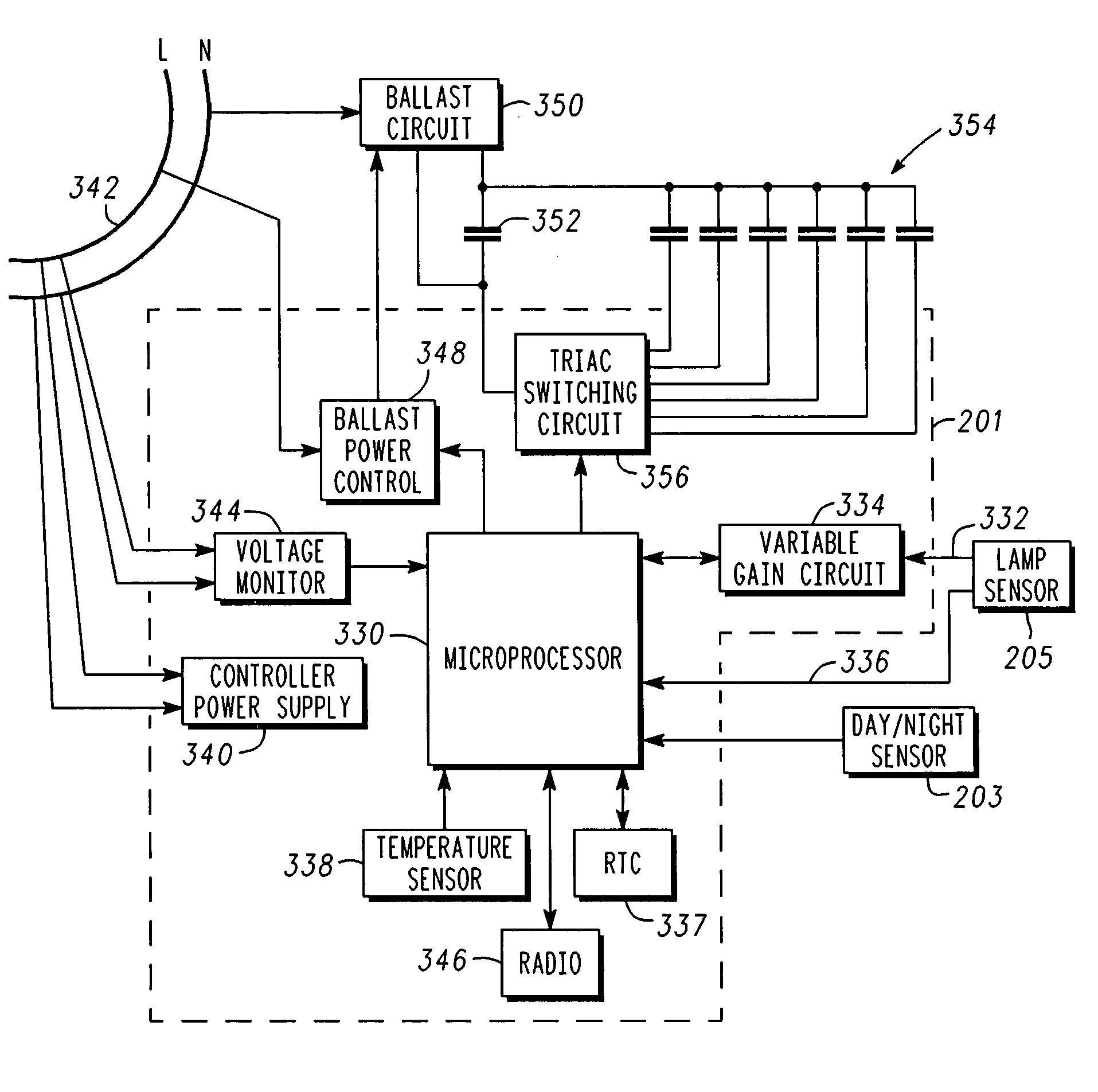
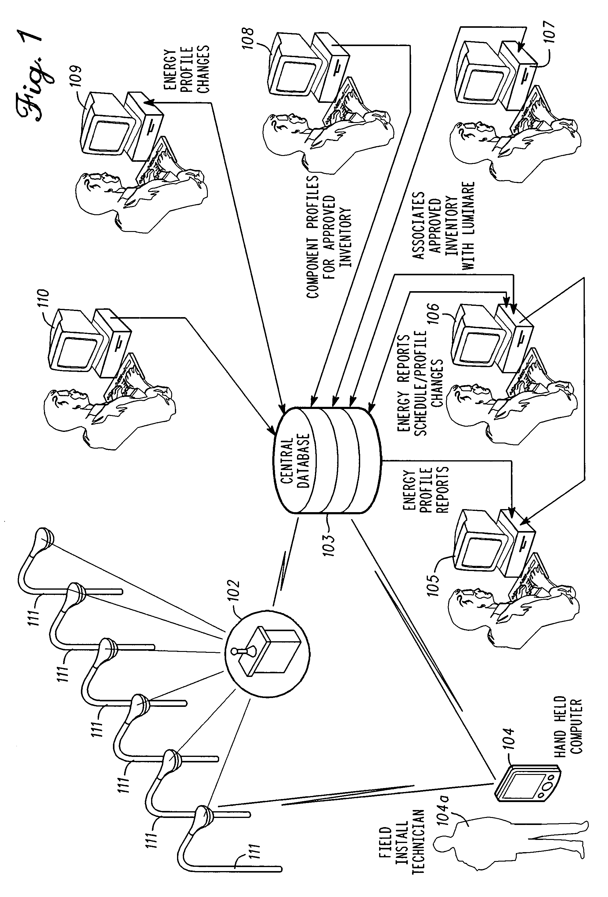
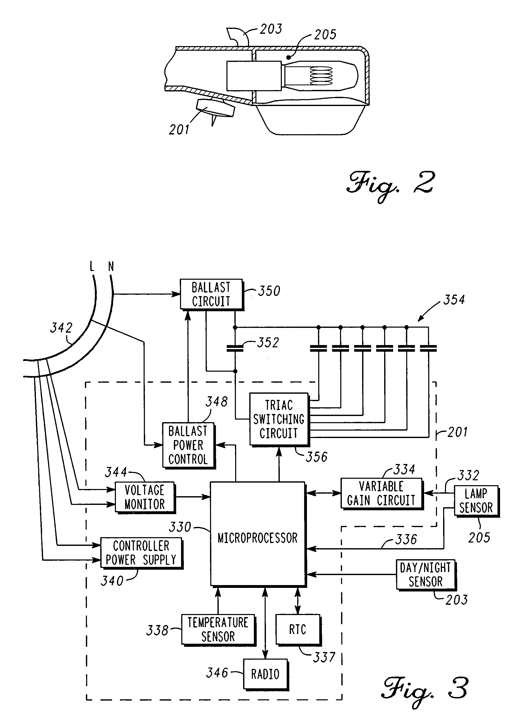
Methods and apparatus associated with monitoring and controlling streetlights include monitoring light levels and voltage levels at corresponding streetlights and controlling the streetlights to set or maintain a particular light output at the respective streetlights or providing power consumption estimates for respective streetlights (streetlight specific metering) based on the voltage levels and light levels. A streetlight controller for a streetlight includes a microcontroller; a first sensor to sense a light level from a lamp within the streetlight; a second sensor operative to sense a voltage level on a power supply for the streetlight; and a switching network coupled with the microcontroller and operative to adjust the light level of the lamp. Methods includes monitoring a light level and voltage level and adjusting a light level, estimating power consumption, or facilitating maintenance in accordance with the light level and voltage level. The methods may be performed all or in part at a streetlight, a local gateway or a central controller and database.

Description

FIELD OF THE INVENTION[0001]This invention relates in general to street lighting plants or systems and more specifically to techniques and apparatus for monitoring and controlling streetlights within such systems.BACKGROUND OF THE INVENTION[0002]Street light systems are known. Traditional methods of monitoring and controlling streetlights are relatively simple. In order to determine that a streetlight is not operating correctly, municipalities typically depend on reports from the public or a maintenance crew. Streetlights are normally turned on at night under the control of a photosensor which may be located on the streetlight or nearby or via time based contactors. Billing for the energy consumption of a streetlight is typically based on the average expected power consumption of the streetlight and the expected number of hours the streetlight will operate based on the length of the night. Maintenance of a streetlight is limited to the replacement of lamps and / or other components on...

Claims


Application Information

Patent Timeline
Patent Type & Authority Patents(United States)
IPC IPC(8): G01W1/12G01R21/00
CPCH02J3/14H05B37/0272H05B37/034H05B41/40Y04S20/246Y02B70/3225Y02B70/3283Y04S20/222Y02B20/72H05B47/22H05B47/11H05B47/19H02J2310/14H02J3/004Y02B70/30H05B47/14Y02B20/40H02J2310/60
Inventor CLELAND, DONALD A.SHARMA, PRATIBHALIGHTBODY, SIMON H.WARRIOR, VELVET
Owner STREETLIGHT INTELLIGENCE INC
Learn More