Flexible support assembly for vehicle tooling plates

a flexible support and tooling plate technology, applied in the field of motor vehicle manufacturing and assembly operations, can solve the problems of costly and time-consuming manufacturing of tooling plates, changing vehicle configurations often require redesigning and re-manufacturing tooling plates, etc., and achieves the effects of convenient and quick modification of the position of the stand, convenient interchangeability, and convenient adjustmen

Inactive Publication Date: 2012-10-23
GM GLOBAL TECH OPERATIONS LLC
View PDF14 Cites 18 Cited by
  • Summary
  • Abstract
  • Description
  • Claims
  • Application Information

AI Technical Summary

Benefits of technology

[0007]The present invention provides a flexible, low-cost support assembly for use in manufacturing and assembly operations, such as vehicle body-chassis marriage applications in high volume production plants. The height of the support assembly is readily adjustable, both manually and robotically, and the location of the stand can be easily and quickly modified. In addition, the support pin is easily interchangeable to allow for varying heights and pin-head configurations. The present design reduces pre-production lead time, as well as production and maintenance costs by eliminating the need for constructing numerous tooling plates and support assemblies for a single manufacturing line, and increasing the flexibility of the process.
[0019]In accordance with yet another embodiment of the present invention, a tooling plate assembly is provided for locating and supporting a fixture for subsequent mounting to a vehicle frame. The tooling plate assembly includes a planar tooling plate with a locating surface on one side thereof. The tooling plate accurately defines a plurality of fastening holes at preselected locations of the locating surface.

Problems solved by technology

As such, a change in vehicle configuration often requires a redesign and re-manufacture of the tooling plate.
Tooling plates are expensive and time consuming to manufacture because the plate material tends to be very expensive, and each opening must be very accurately located with relation to the other openings to ensure proper fixture orientation.

Method used


Image

  • Flexible support assembly for vehicle tooling plates
  • Flexible support assembly for vehicle tooling plates
  • Flexible support assembly for vehicle tooling plates

Examples


Embodiment Construction

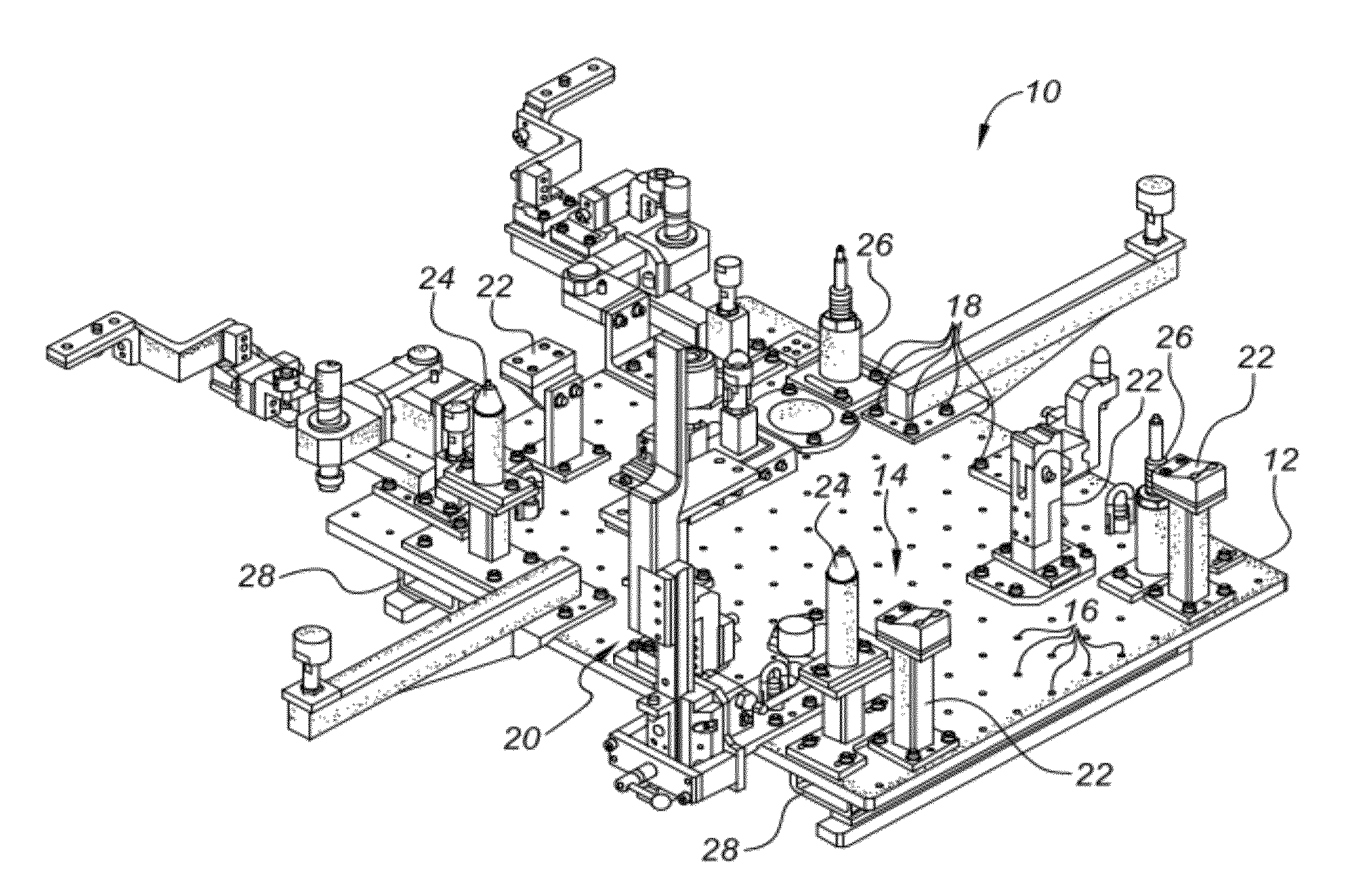
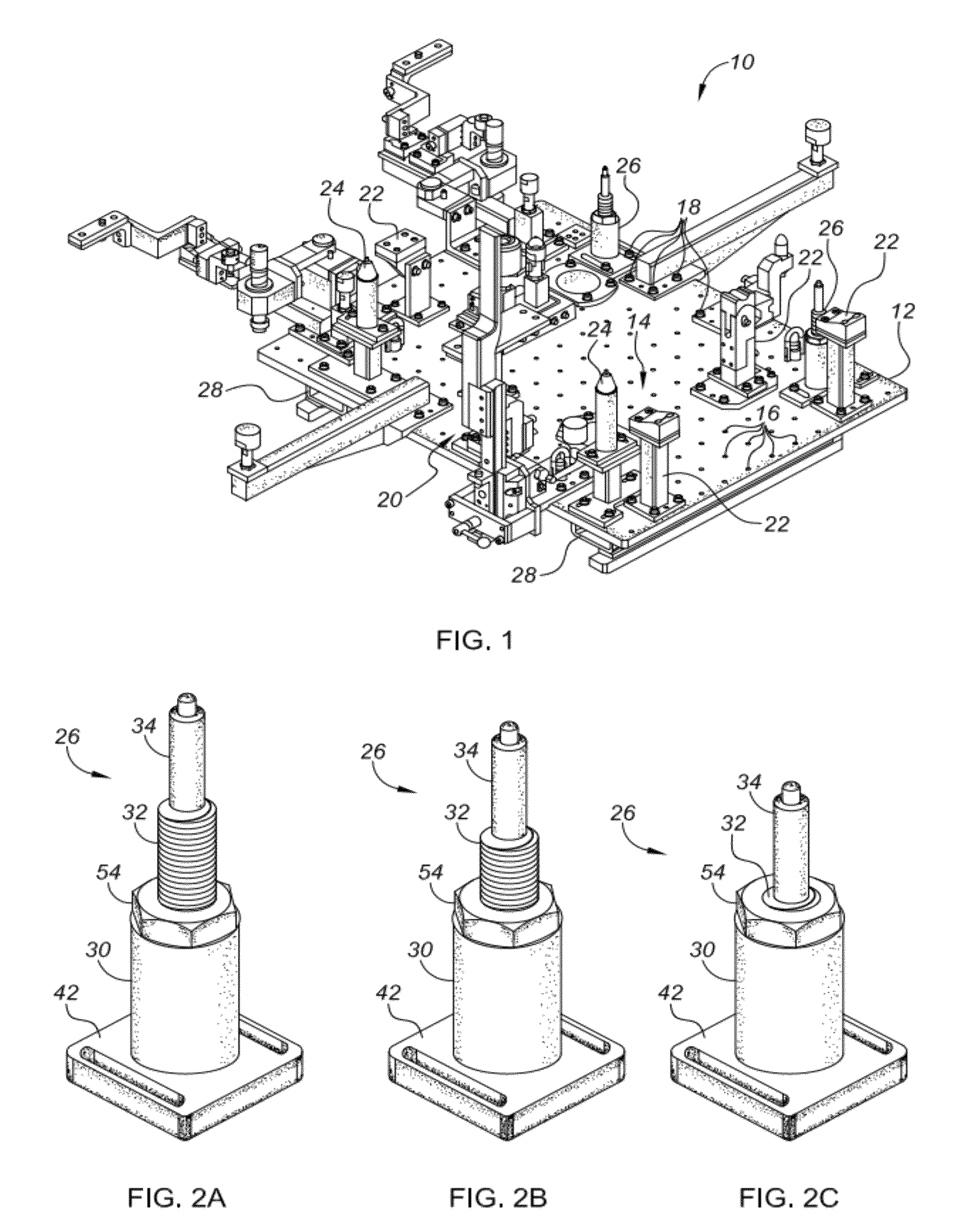
[0027]Referring to the drawings, wherein like reference numbers refer to like components throughout the several views, a representative tooling plate assembly with which the present invention may be incorporated and practiced is shown in FIG. 1, identified generally as 10. The tooling plate assembly 10 is intended for use in body-chassis marriage applications in a high volume, flexible manufacturing automobile production plant. It should be readily understood, however, that the present invention may be employed in other manufacturing and assembly operations in the automotive industry, as well as other industries. Moreover, the particular arrangement shown in FIG. 1 is merely provided for exemplary purposes. As such, the present invention is by no means limited to the particular tooling plate configuration shown in the drawings. Finally, the drawings presented herein are not to scale and are provided purely for instructional purposes. Thus, the individual and relative dimensions show...


PUM


Abstract

The present invention provides a flexible support assembly for supporting and / or locating a fixture on a tooling plate. The support assembly includes a stanchion with a bore, and a threaded portion on an inner-diameter surface thereof. A base plate is attached to, and configured to repositionably fix the stanchion to the tooling plate. A cylindrical sleeve with a threaded portion on an outer-diameter surface thereof is threadably engaged with the stanchion, whereby the sleeve is operable to telescope with respect to the stanchion between a first, lowest position and a second, highest position. A nut is threadably engaged with the sleeve to lock the sleeve at any predetermined position between the first and second positions. A locator pin is releasably engaged with the sleeve at a first end thereof. The locator pin has a protrusion projecting outward from a second opposing end thereof for engaging a pinhole in the fixture.

Description

TECHNICAL FIELD[0001]The present invention relates generally to motor vehicle manufacturing and assembly operations, and more specifically to tooling plate supports used in vehicle body-chassis marriage applications.BACKGROUND OF THE INVENTION[0002]A contemporary motor vehicle, such as the modern-day automobile, consists of thousands of individual components. It has been, and remains conventional practice in the automotive industry for the vehicle body (or frame) to be built as an open structure into which are fitted and fixed all the constituent parts and equipment of the vehicle. A continuously moving conveyor, which is part of an overall mass production assembly line, carries the vehicle assembly through an assortment of work stations where various parts are fitted to the vehicle assembly to ultimately produce a completed vehicle.[0003]In modern vehicle assembly operations, it is customary to preassemble the individual components of the vehicle chassis, such as the engine, transm...

Claims


Application Information

Patent Timeline
Patent Type & Authority Patents(United States)
IPC IPC(8): B25B11/00
CPCB62D65/10B62D65/12B62D65/18B23P2700/50
Inventor GAO, DALONGMARIN, SAMUEL P.MARIN, LEGAL REPRESENTATIVE, SHELIA A.MENASSA, ROLAND J.
Owner GM GLOBAL TECH OPERATIONS LLC
Why Eureka
Try Eureka