Mortise lock assembly

a technology of mortise locks and parts, applied in the field of mortise locks, can solve the problems of affecting the installation process of right-hand doors, and affecting the safety of the mortise locks

Active Publication Date: 2012-10-23
TOWNSTEEL
View PDF64 Cites 35 Cited by
  • Summary
  • Abstract
  • Description
  • Claims
  • Application Information

AI Technical Summary

Benefits of technology

[0017]In a yet more detailed embodiment, a faceplate-accessible user-selectable clutchworks is operatively coupled to the user-actuated clutch. The clutchworks which in one embodiment comprises a pair of parallel, interlinked slides geared to reciprocate in opposite directions is operable to drive a clutch lever arm and the clutch links it carries between engaged and disengaged positions. An escapement mechanism enables reciprocating operation of the clutchworks when the spindle hub subassembly is misaligned with the coaxial cam subassembly.

Problems solved by technology

One disadvantage of door-handle locking locksets is that turning the outside door handle can place a significant amount of potentially damaging torque on the door-handle-locking mechanism inside the lock body.
Often, one or more biasing springs must also be dismounted and remounted—making the conversion process a more difficult and cumbersome process.
Converting the left-handed mortise latch and lock body assembly 10 into one adapted for right-hand door installation is a tedious and cumbersome process.
Not all mortise locksets require so cumbersome a process to reverse their handing.
However, misalignment of the inside and outside door handles can prevent a person from engaging the stop or clutch works.
However, the blocker assembly is disabled if the outside door handle is in a position that is engaged to retract the latchbolt assembly.
If the lockset also includes a finger-operable arrangement in the front plate for restoring the outside door handle to an operating condition, there is a danger—particularly with non-deadbolted mortise locks installed in left- or right-handed “reverse” doors (where the door swings out of the access-restricted space)—that an intruder could “card” the finger operable arrangement in order to disable the blocker.

Method used


Image

  • Mortise lock assembly
  • Mortise lock assembly
  • Mortise lock assembly

Examples


Embodiment Construction

[0069]In describing preferred and alternate embodiments of the technology described herein, as illustrated in FIGS. 1-39, specific terminology is employed for the sake of clarity. The technology described herein, however, is not intended to be limited to the specific terminology so selected, and it is to be understood that each specific element includes all technical equivalents that operate in a similar manner to accomplish similar functions.

[0070]I. Conventional Elements

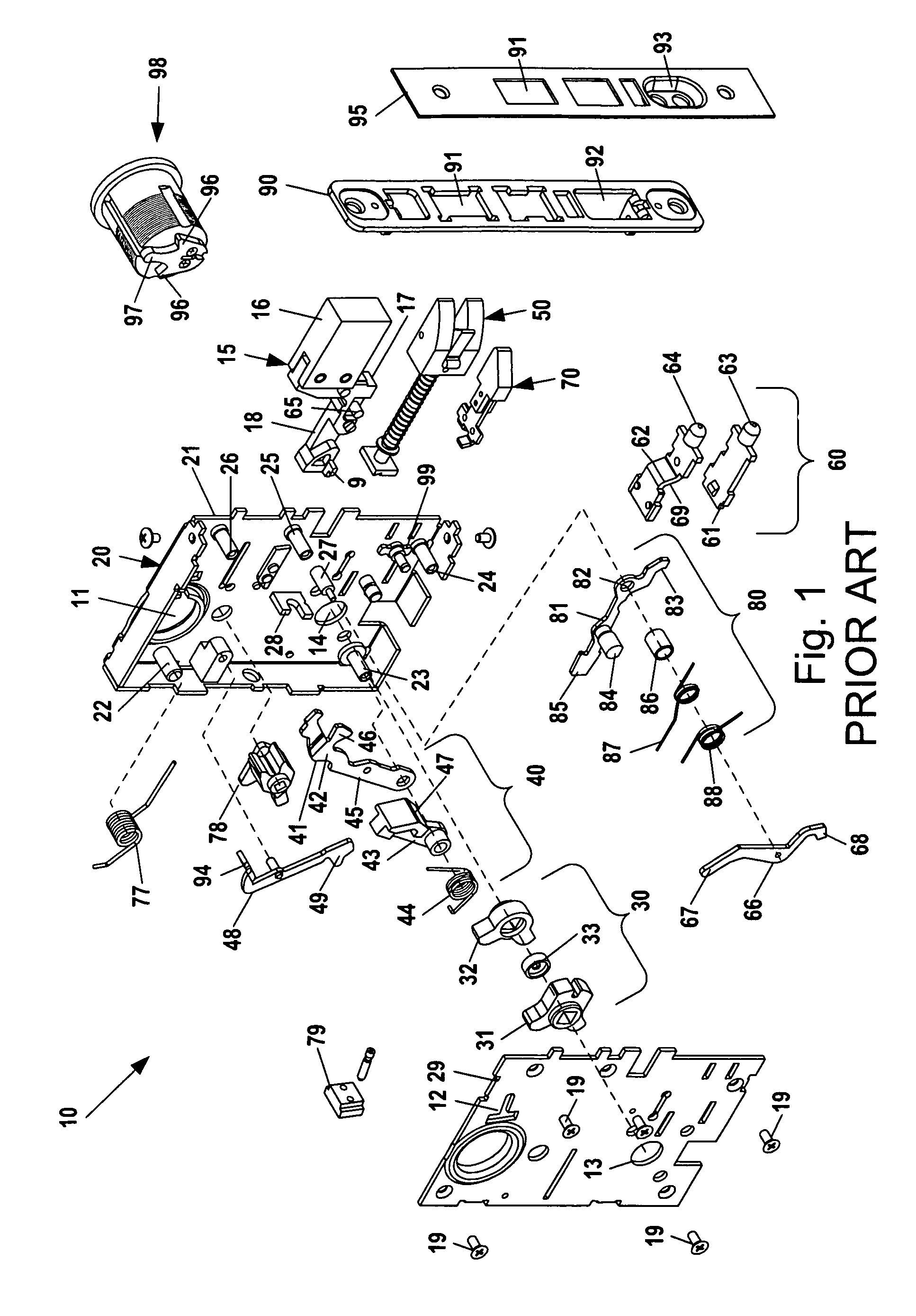
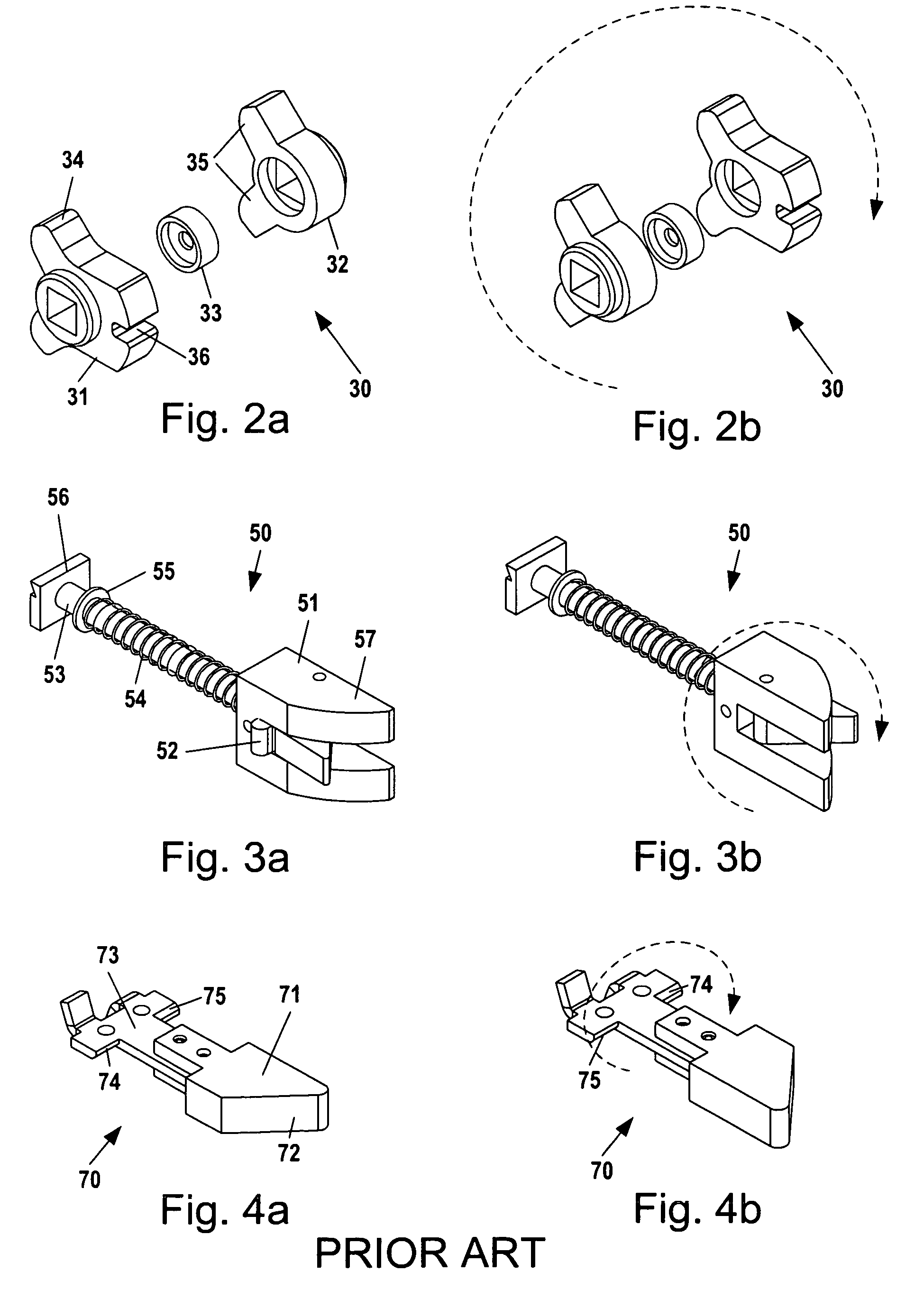
[0071]To highlight some of the novel components in the present invention, comparison is made with FIGS. 1-4b, which illustrates a prior art mortise latch and lock body 10. The interaction of some of the conventional elements is also revealed in FIGS. 8 and 9. It should be noted, however, that FIGS. 8 and 9 are not prior art locksets, because they contain several new elements according to the present invention.

[0072]The mortise latch and lock body assembly 10 mounts in a door opposite a strike plate on a doorjamb (n...


PUM


Abstract

Several new components are provided for a mortise lock. First, a non-handed clutching assembly, including a pair of spindle hubs rotatable within a pair of outer operating cams, is provided for a mortise lock. Second, a spindle-mounted lock-handing selector—which can be removed from one side of the lockset body while the lockset body is installed in the mortise of a door—is provided to set the handing of the clutching assembly. Third, an escapement mechanism is provided for a reciprocating-slide-based clutchworks, enabling the slides to move into a position biasing a clutch lever arm toward a hub-coupling position, even if the outer and spindle hubs are misaligned. Fourth, a guardbolt-actuated blocking assembly for a lockset is provided to block movement of the stop works or clutchworks when the door is closed and the outside door handle is disabled.

Description

FIELD OF THE INVENTION[0001]This invention relates generally to locks, and more specifically, to mortise locks.BACKGROUND OF THE INVENTION[0002]Mortise locksets are a type of lock that is fitted into a rectangular cavity, called a “mortise,” that is cut into the side of a door. Mortise locksets typically comprise a rectangular lock body that is inserted into the mortise, lock trim (including inside and outside trim plates, doorknobs, and / or door handles), a strike plate or box keep that lines a cavity in the door jamb, and a keyed cylinder that operates the locking / unlocking function. A mortise lockset includes a typically self-latching main bolt or latchbolt, and optionally may also include a deadbolt and / or guardbolt. The lock body typically comprises a case assembly and cover that house the keyed cylinder and several levers, springs, and other moving parts used to bias, extend and / or retract the various bolts.[0003]Mortise locksets come in both door-handle locking and door-handle...

Claims


Application Information

Patent Timeline
Patent Type & Authority Patents(United States)
IPC IPC(8): E05C5/04
CPCE05B55/00E05B55/06E05B55/12E05B59/00E05B63/0056E05B63/04E05B63/044E05B63/16E05B65/1086E05B2063/0082Y10T70/5226Y10T70/5372Y10T70/5389Y10T70/5394Y10T70/5832Y10T70/8865Y10T292/0839Y10T292/0868Y10T292/0969Y10T292/0977Y10T292/0994Y10T292/102Y10T292/1097Y10T292/59
Inventor MOON, CHARLES W.
Owner TOWNSTEEL
Why Eureka
Try Eureka