Surgical treatment apparatus

a technology for surgical treatment and apparatus, applied in the field of surgical treatment apparatus, can solve the problems of difficult operation, obstructed treatment area, unable to be seen in some cases, and difficult observation while carrying out treatmen

Active Publication Date: 2012-10-23
OLYMPUS CORP
View PDF20 Cites 713 Cited by
  • Summary
  • Abstract
  • Description
  • Claims
  • Application Information

AI Technical Summary

Problems solved by technology

For this reason, the operation is difficult.
When the endoscope is used to perform observation during treatment or to check for any remaining tumor after the treatment, the treatment area is obstructed by the ribs and cannot be viewed in some cases.
When transurethral manipulation is used, it is difficult to perform observation while carrying out treatment because the inlet of the opening is narrow and there is no space for forming a plurality of openings.

Method used


Image

  • Surgical treatment apparatus
  • Surgical treatment apparatus
  • Surgical treatment apparatus

Examples


first embodiment

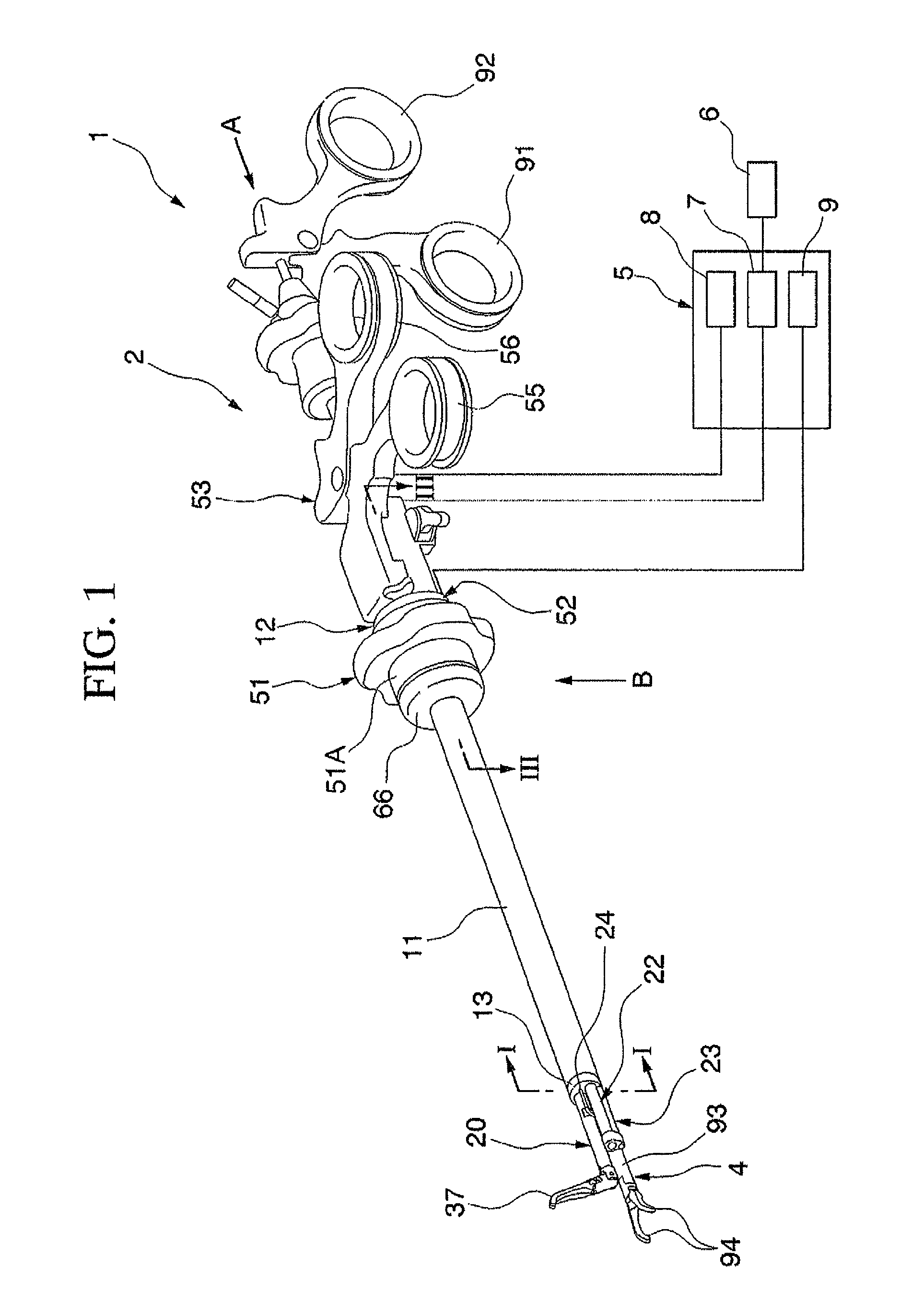
[0039]As shown in FIG. 1 in a surgical treatment apparatus 1, a long, thin and hard insertion section 3 extends from an operation section 2 that is operated outside the body by the operator, and forceps 4 serving as a replaceable treatment instrument are inserted into the insertion section 3. Furthermore, the surgical treatment apparatus 1 is connected to a control unit 5, whereby it is possible to carry out image processing and display on a monitor 6 as described later. Although the forceps 4 are shown in FIG. 1 as a treatment instrument, a clip or the like may also be used.

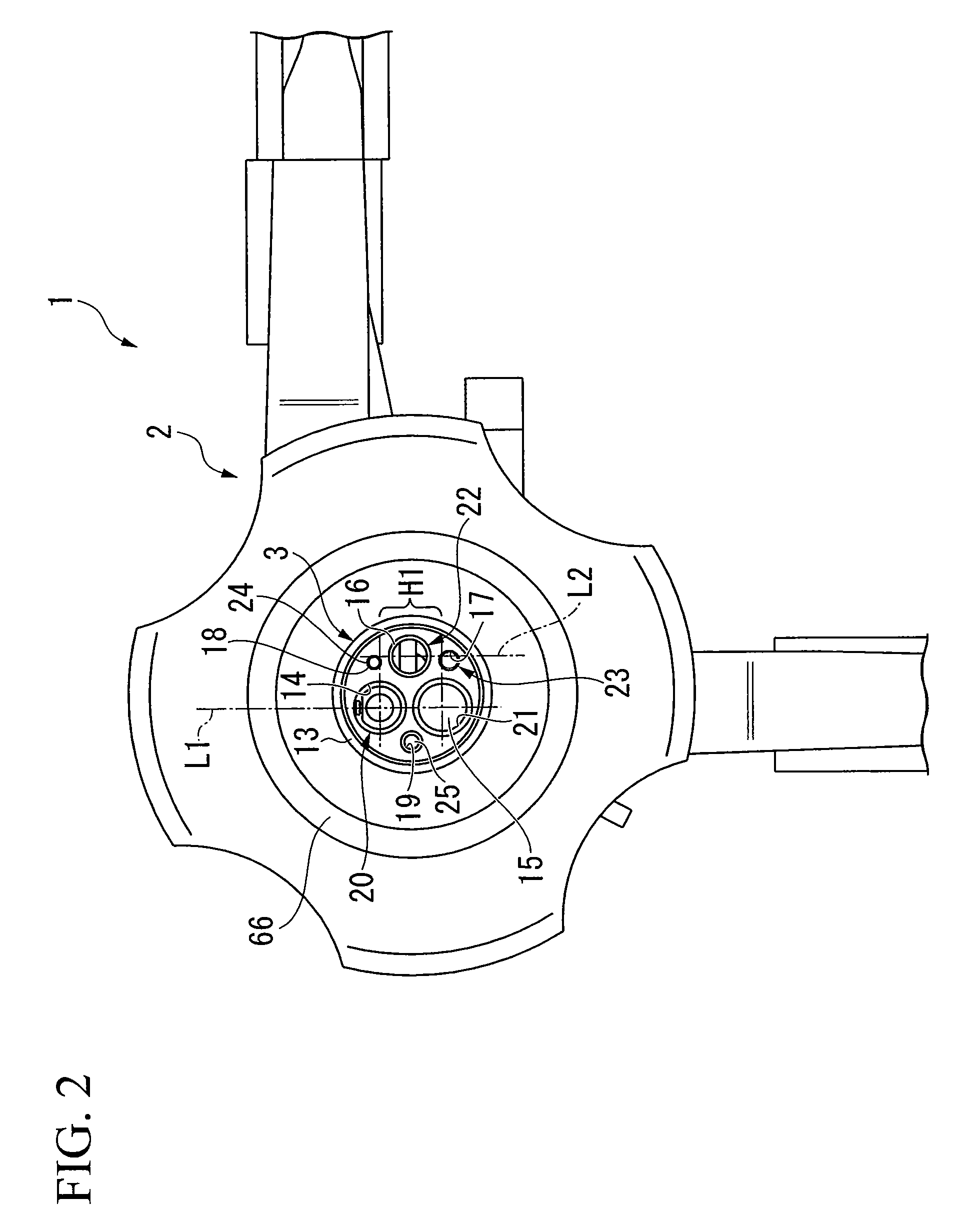
[0040]The insertion section 3 has a cylindrical outer sheath 11. An end cap 12 is fitted on the base portion on the hand side of the operator, and an end cap 13 is fitted on the tip portion that is inserted into the body. As shown in FIG. 1 and FIG. 2, six ducts 14, 15, 16, 17, 18 and 19 are formed in the end cap 13 parallel with the axial direction of the insertion section 3. Pivotable forceps 20 serving as a t...

second embodiment

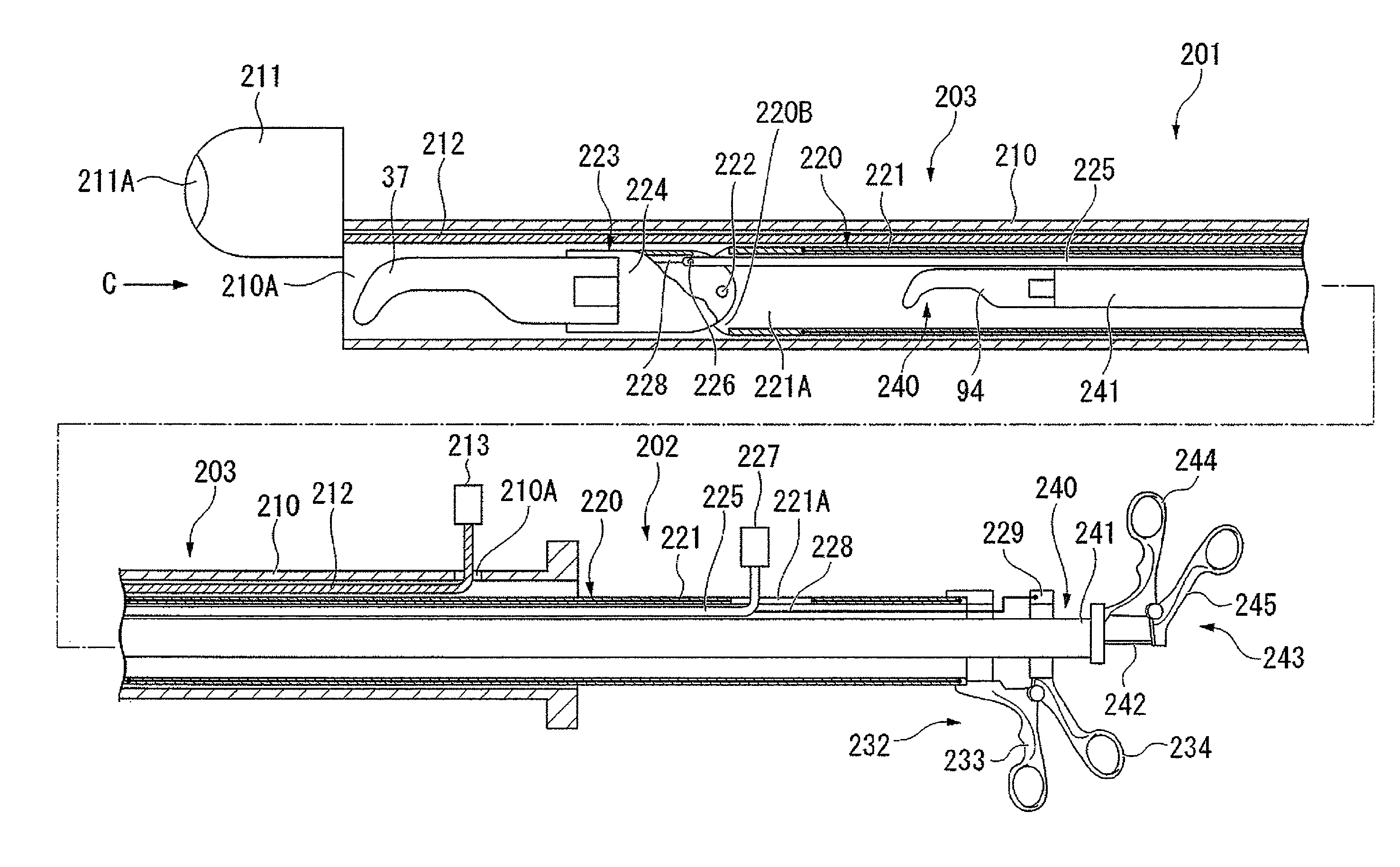
[0072]This embodiment is characterized in that two treatment instruments and an image pickup device can be disposed concentrically with one another. As shown in FIG. 20, in a surgical treatment apparatus 201, a long, thin and hard insertion section 203 extends from an operation section 202 that is operated outside the body by the operator. The insertion section 203 has a cylindrical outer sheath 210, and an image pickup device 211 is disposed at the tip portion thereof that is inserted into the body. The outside diameter of the image pickup device 211 is substantially equal to that of the outer sheath 210, and the image pickup device 211 provides illumination and takes images through a transparent cover 211A disposed at the tip portion thereof. The image pickup device 211 is supported using a rotation rod 212 passed through the outer sheath 210. The rotation rod 212 is freely rotatably passed through at a position near the inner circumferential face and offset from the axis line of ...


PUM


Abstract

A surgical treatment apparatus according to the present invention includes an outer sheath, extending from a base portion subject to an operator's hand to the tip subject to insertion into a body cavity, that is provided with a working channel through which a treatment instrument can be passed; an image pickup device disposed at the tip portion of the outer sheath; and pivotable forceps disposed at the tip portion of the outer sheath, supported on a supporting section protruding in the axial direction via a joint being bent away from the working channel, and having a pair of forceps members arranged so as to be freely opened / closed, wherein the image pickup device is disposed at a position between the axis line of the supporting section and the axis line of the working channel and offset from an imaginary line connecting the two axis lines.

Description

BACKGROUND OF THE INVENTION[0001]1. Field of the Invention[0002]The present invention relates to an apparatus for carrying out surgical treatment.[0003]2. Background Art[0004]When a medical practice, such as observation or treatment, is carried out on human organs and the like, treatment instruments, such as an endoscope and forceps, are occasionally inserted through a natural opening in a living body. When a medical practice is carried out in an abdominal cavity, a plurality of openings are formed in the abdominal wall, instead of making a large incision in the abdominal wall. Treatment instruments, such as an endoscope and forceps, are inserted, one for each opening, in some cases. Since this is made possible only by forming small openings in the abdominal wall, it is advantageous that invasion into the patient is minimal and that the patient can recuperate rapidly.[0005]For example, when a tumor has developed in the bladder, forceps are transurethrally inserted into the bladder t...

Claims


Application Information

Patent Timeline
Patent Type & Authority Patents(United States)
IPC IPC(8): A61B1/00
CPCA61B17/29A61B1/00087A61B1/018A61B1/05A61B2017/00296A61B2017/00199A61B2017/00314A61B2017/00738A61B2019/5217A61B2019/467A61B2017/2906A61B2017/2927A61B2090/3614A61B2090/067
Inventor DEJIMA, TAKUMIMINOSAWA, RYOKOGASAKA, TAKAHIRO
Owner OLYMPUS CORP
Why Eureka
Try Eureka