
Motion-compensated coronary flow from projection imaging

a technology of projection imaging and motion compensation, applied in the field of medical imaging, can solve problems such as volume obstruction, and achieve the effect of precise flow and pressure decline determination

Active Publication Date: 2012-10-23
KONINK PHILIPS ELECTRONICS NV
View PDF9 Cites 18 Cited by
  • Summary
  • Abstract
  • Description
  • Claims
  • Application Information

AI Technical Summary

Benefits of technology

The patent describes an examination apparatus for motion compensated determination of flow dynamics in a region of interest, such as a coronary artery. The apparatus uses markers to track the movement of the region and compensates for the motion by performing motion compensation on the basis of the markers. The motion compensation can be performed using a dedicated flow run or a standard acquisition run. The apparatus can also compensate for the rotation of the markers or the pulsation effects of the contrast agent concentration. The method can be applied to vessels in the lung and can compensate for the variability of the flow over the cardiac cycle. The apparatus can also include compensation for the variability of the contrast agent injection time or the inclusion of the variability in a subsequent analysis. Overall, the patent provides a technical solution for accurately determining flow dynamics in a region of interest.

Problems solved by technology

Obstructed volume flow and increased pressure decline at a coronary lesion are the major cause of coronary heart disease.

Method used


Image

  • Motion-compensated coronary flow from projection imaging
  • Motion-compensated coronary flow from projection imaging
  • Motion-compensated coronary flow from projection imaging

Examples


Embodiment Construction

[0043]The illustration in the drawings is schematic. In different drawings, similar or identical elements are provided with the same reference numerals.

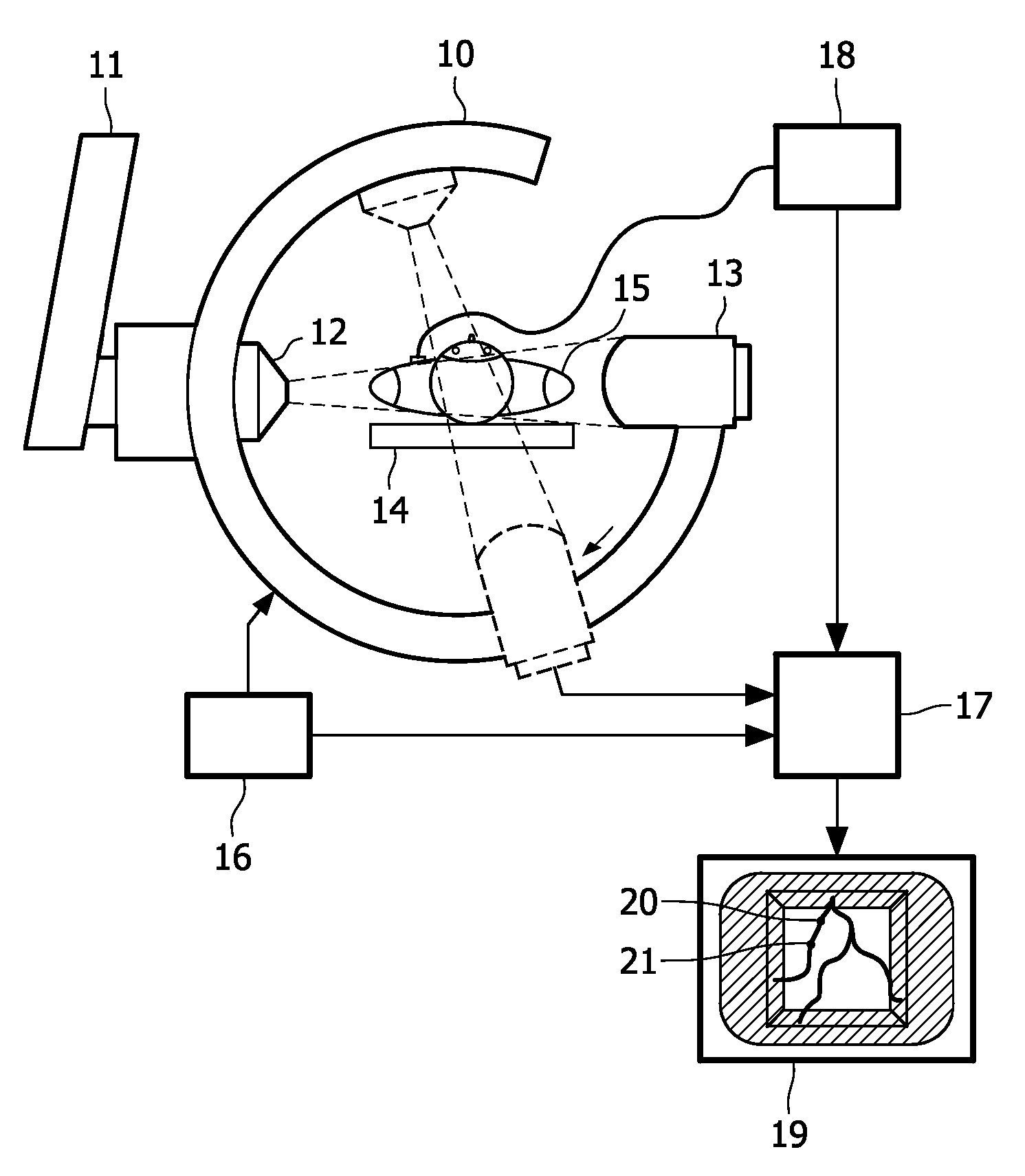
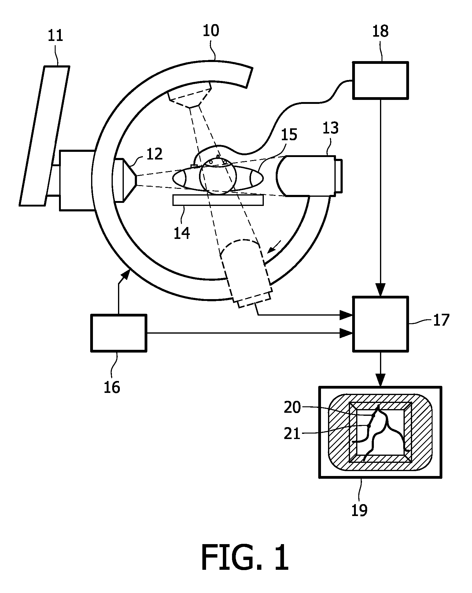
[0044]FIG. 1 shows a simplified schematic representation of an examination apparatus according to an exemplary embodiment of the present invention.

[0045]The invention may be applied in the field of two-dimensional imaging like fluoroscopic x-ray, x-ray angiograms, ultrasound, or video-imaging. In such a case, the examination may be performed with conventional x-ray systems. Furthermore, the invention may be applied in the field of three-dimensional imaging, such as three-dimensional rotational x-ray imaging or three-dimensional rotational angiography imaging.

[0046]The invention may be particularly used when a motion compensated coronary flow has to be determined from projection imaging but may as well be used when a change of pressure has to be detected in a vessel.

[0047]The apparatus depicted in FIG. 1 is a C-arm x-ray examination a...


PUM


Abstract

Diagnostic angiograms only provide the projected lumen of a coronary, which is only an indirect measure of blood flow and pressure decline. According to an exemplary embodiment of the present invention, a motion compensated determination of a flow dynamics and a pressure decline for stenosis grading is provided, in which the motion compensation is performed on the basis of a tracking of a first position of a first marker and a second position of a second marker in the projection data set. This may provide for a robust and precise flow dynamics and pressure decline determination.

Description

FIELD OF THE INVENTION[0001]The invention relates to the field of medical imaging. In particular, the invention relates to an examination apparatus for motion compensated determination of flow dynamics from an image sequence of an object of interest, to a method of motion compensated determination of flow dynamics, an image processing device, a computer-readable medium and a program element.TECHNICAL BACKGROUND[0002]Stenosis grading from contrasted x-ray angiograms is of major interest for minimally invasive treatment of diseased coronaries in the cardiac cathlab. Obstructed volume flow and increased pressure decline at a coronary lesion are the major cause of coronary heart disease. For a well founded treatment decision, it is important in daily clinical routine to assess the severity of such stenoses. Currently, subjective visual inspection of coronary angiograms or the determination of the pressure decline using an intravascular pressure gauge are used to assess this severity. Co...

Claims


Application Information

Patent Timeline
Patent Type & Authority Patents(United States)
IPC IPC(8): G06K9/00
CPCA61B6/481A61B6/507A61B6/527A61B8/5276A61B6/504A61B6/503
Inventor BREDNO, JOERGWEESE, JUERGENGROTH, ALEXANDRA
Owner KONINK PHILIPS ELECTRONICS NV
Learn More