
Femto-cell power control using idle-mode user equipment in a cellular communication system

a cellular communication system and user equipment technology, applied in the field of interference in wireless cellular communication systems, can solve the problems of large number of small underlay cells within a single macro-cell, ad hoc introduction of underlaying femto-cells, and inability to change,

Active Publication Date: 2012-10-23
GOOGLE TECH HLDG LLC
View PDF13 Cites 20 Cited by
  • Summary
  • Abstract
  • Description
  • Claims
  • Application Information

AI Technical Summary

Benefits of technology

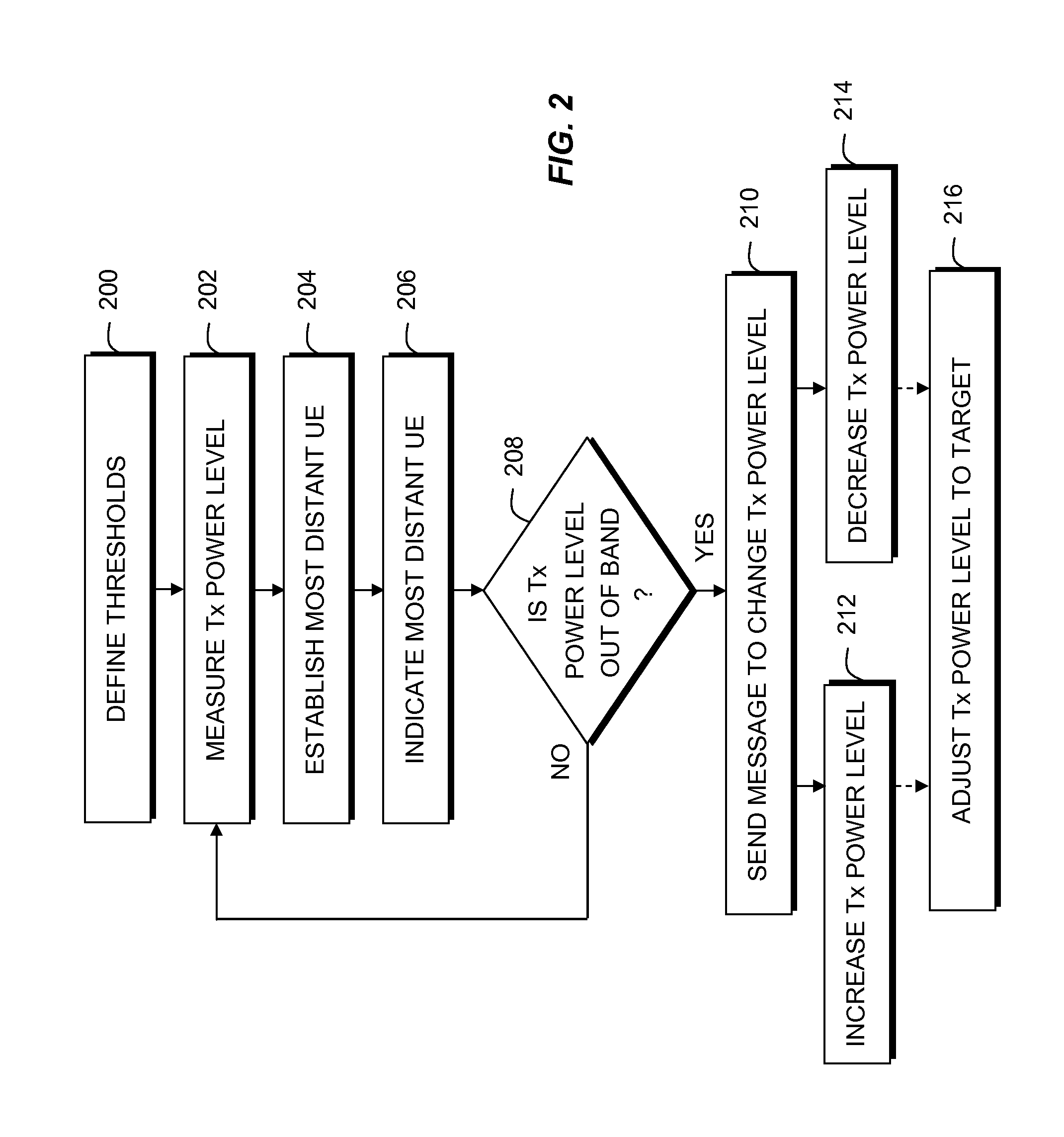
The present invention provides a method for controlling power in a wireless communication system using idle-mode user equipment. The method defines power levels for signal transmissions and an operating power band between them. If the user equipment detects that the power level is outside of the operating band, a message is sent to change the power level. This helps to optimize power usage and improve the overall performance of the wireless communication system.

Problems solved by technology

A widespread introduction of such a system could result in a very large number of small underlay cells within a single macro-cell.
However, a problem arises in the ad hoc introduction of underlaying femto-cells, such as residential deployments of femto-cell HeNBs where the deployment process is incremental, unilateral, and changeable.
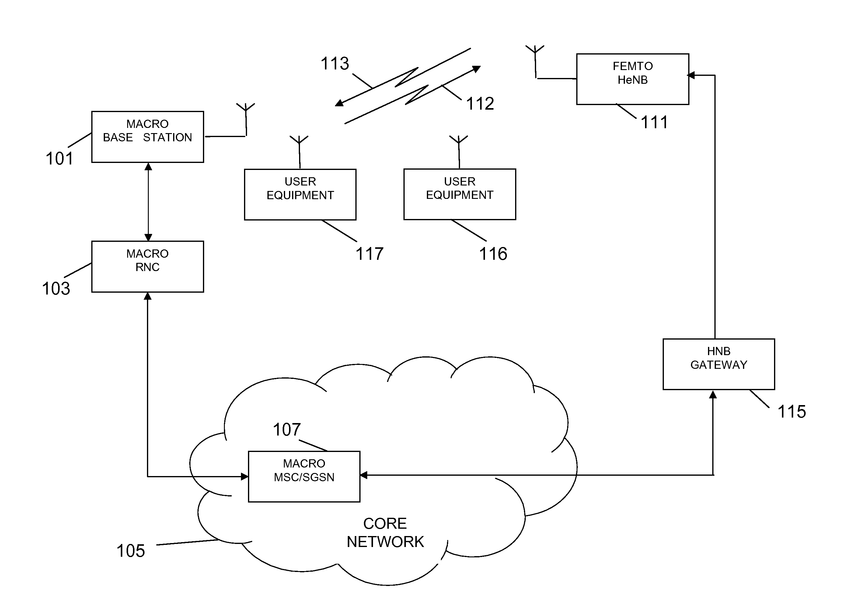
In particular, without coordination between the RNC of the macro layer and the HeNB layer, and considering a much smaller dynamic range of power control at the HeNB, there are cases where the macro layer can suffer interference from the control pilot channel power of the HeNB in close proximity thereto and vice versa.
Although this minimum power level can be determined easily for connected-mode UEs according to the dedicated signalling between the HeNB and the connected-mode UEs, it is difficult to obtain the minimum power level to ensure coverage for idle-mode UEs as no dedicated signalling exists between the HeNB and the idle-mode UEs.
No settings, regardless of how optimal, are stable for long, and they will change over time.

Method used


Image

  • Femto-cell power control using idle-mode user equipment in a cellular communication system
  • Femto-cell power control using idle-mode user equipment in a cellular communication system
  • Femto-cell power control using idle-mode user equipment in a cellular communication system

Examples


Embodiment Construction

[0011]Turning to the drawings, wherein like reference numerals refer to like elements, the invention is illustrated as being implemented in a suitable environment. The following description is based on embodiments of the invention and should not be taken as limiting the invention with regard to alternative embodiments that are not explicitly described herein.

[0012]The present invention provides a technique to configure HeNB control channel power in response to reports from idle-mode UEs. The present invention also minimizes femto-cell transmission power while providing coverage for UEs authorized for that femto-cell and avoids numerous control messages between UEs and their serving femto-cell while providing information to the femto-cell to best enable downlink control channel transmission power reduction. Note that the current invention is mainly focused on optimizing the control channel transmission power and rate in order to dynamically adjust cell footprint to best meet the need...


PUM


Abstract

Disclosed is a method for providing power control using idle-mode user equipment attached to a cell in a wireless communication system. First and second higher power level thresholds for signal transmissions of a cell are defined, wherein the first power level has a defined offset higher than a minimum required power level, and wherein the first and second power level thresholds define an operating power band therebetween. The user equipment measures a signal transmission power level. If the idle-mode user equipment determines that the signal transmission power level falls outside of the operating power band, then a message is sent to affect a change in signal transmission power level.

Description

CROSS-REFERENCE TO RELATED APPLICATIONS[0001]The present application claims priority to U.S. Provisional Patent Application 61 / 185,753, filed on Jun. 10, 2009.FIELD OF THE INVENTION[0002]The present invention is related generally to interference in a wireless cellular communication system and, more particularly, to femto-cell power control using idle-mode user equipment in a cellular communication system.BACKGROUND OF THE INVENTION[0003]A method which has been used to increase the capacity of cellular communication systems depends upon the concept of hierarchical cells wherein a macro-cell layer is underlayed by a layer of typically smaller cells having coverage areas within the coverage area of the macro-cell. In this way, the smaller cells, known as micro-cells, pico-cells, or femto-cells (hereinafter collectively referred to as femto-cells) are located within the same coverage area as larger overlaying macro cells. The femto-cells have much smaller coverage thereby allowing a muc...

Claims


Application Information

Patent Timeline
Patent Type & Authority Patents(United States)
IPC IPC(8): H04B7/00
CPCH04W52/287H04W52/367
Inventor HARRIS, JOHN M.HAN, GUANG
Owner GOOGLE TECH HLDG LLC
Learn More