Microcontroller and control method therefor

a microcontroller and control method technology, applied in the field of microcontrollers, can solve the problems of inability to control the operation of the peripheral functions, the clock function is reset and forced to stop operating, and the value obtained in the peripheral functions cannot be used

Inactive Publication Date: 2012-10-23
RENESAS ELECTRONICS CORP
View PDF19 Cites 9 Cited by
  • Summary
  • Abstract
  • Description
  • Claims
  • Application Information

AI Technical Summary

Benefits of technology

[0016]In the microcontroller according to the present invention, even of the power supply voltage becomes equal to or lower than the first voltage value and the CPU provided in the microcontroller is reset and deactivated, the real-time clock is not stopped unless the power supply voltage becomes equal to or lower than the second voltage value that is lower than the first voltage value.
[0017]According to the present invention, even if the power supply voltage drops and the CPU is reset, the real-time clock is not reset. Consequently, it is unnecessary to set the time function again.

Problems solved by technology

However, when a main battery or an AC power supply for supplying power to a device is disconnected, or when a voltage supplied from a battery drops, for example, the clock function is reset and forced to stop operating.
Accordingly, when the CPU is reset, the operations of the peripheral functions cannot be controlled and the values obtained in the peripheral functions cannot be used.
As a result, user-friendliness in using the device having the microcontroller is impaired.
However, an output voltage drops during a process in which the capacitance is discharged.
As a result, it is necessary to prepare another chip, which leads to an increase in manufacturing costs due to an increase in substrate area, an increase in the number of manufacturing processes, and the like.
In the prior art, the clock function of the real-time clock provided in the microcontroller cannot operate continuously at low voltage.

Method used


Image

  • Microcontroller and control method therefor
  • Microcontroller and control method therefor
  • Microcontroller and control method therefor

Examples


first embodiment

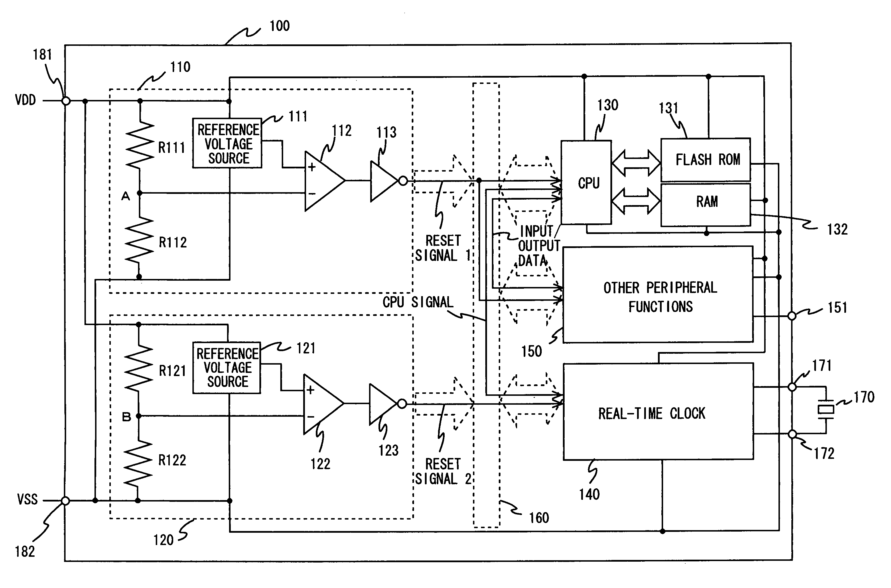
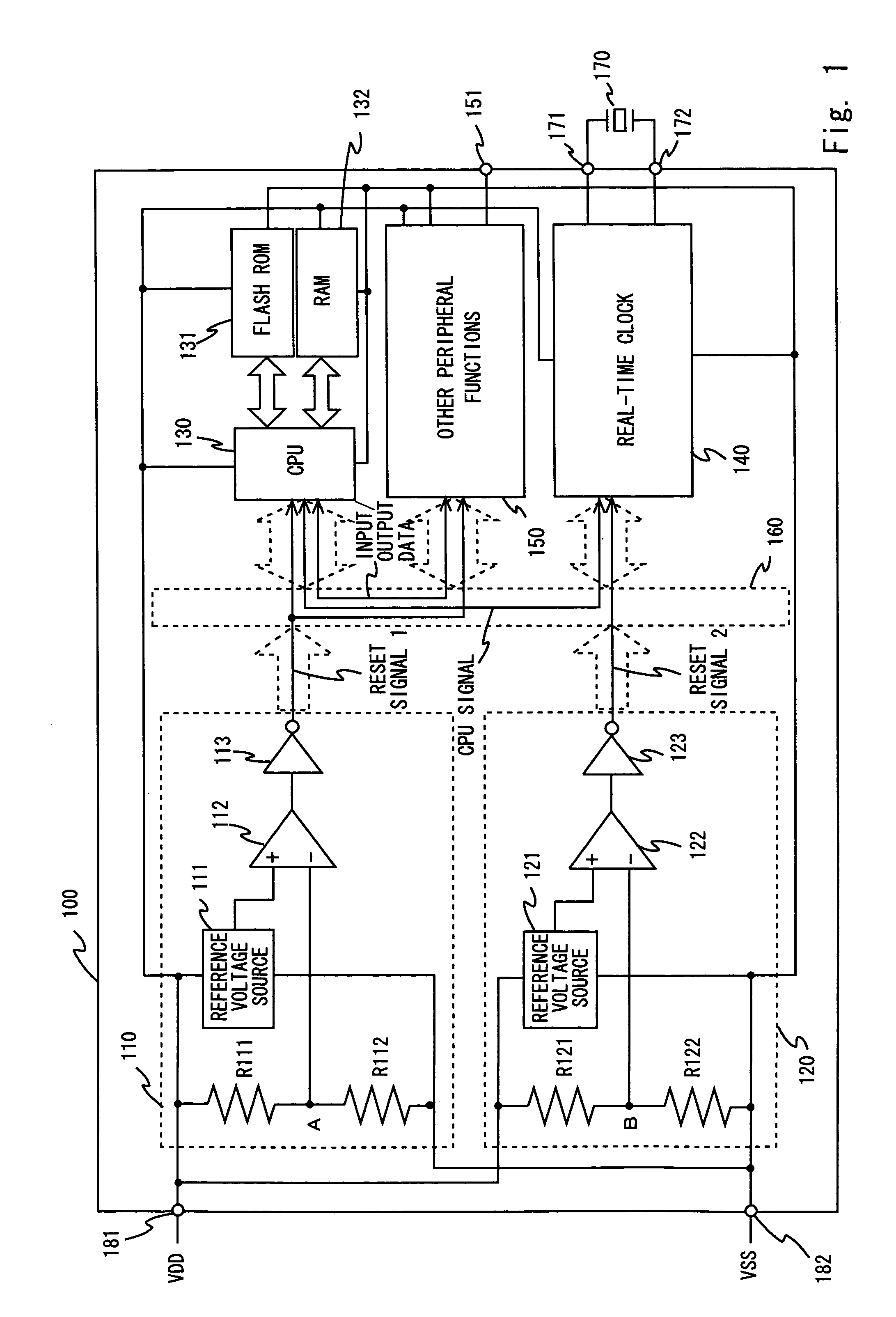
[0026]Hereinafter, specific embodiments to which the present invention is applied will be described in detail with reference to the drawings. FIG. 1 shows an example of the configuration of a microcontroller 100 according to a first embodiment of the present invention.

[0027]The microcontroller 100 includes a low-voltage detection circuit 110, a low-voltage detection circuit 120, a CPU 130, a flash ROM 131, a RAM 132, a real-time clock 140, other peripheral functions 150, and an internal bus 160, which are formed on a single chip. Further, the microcontroller 100 includes a high-potential side power supply voltage terminal 181, a low-potential side power supply voltage terminal 182, external terminals 171 and 172, and a data input / output terminal 151. The high-potential side power supply voltage terminal 181 and the low-potential side power supply voltage terminal 182 supply a power supply voltage VDD and a voltage VSS at GND level, respectively. The external terminals 171 and 172 ar...


PUM


Abstract

Provided is a microcontroller including: a first low-voltage detection circuit to detect that a power supply voltage is equal to or lower than a first voltage value; a second low-voltage detection circuit to detect that the power supply voltage is equal to or lower than a second voltage value, the second voltage value being lower than the first voltage value; a CPU to stop operating when the first low-voltage detection circuit detects that the power supply voltage is equal to or lower than the first voltage value; and a real-time clock to continue operating unless the second low-voltage detection circuit detects that the power supply voltage is equal to or lower than the second voltage value, in which the first low-voltage detection circuit, the second low-voltage detection circuit, the CPU, and the real-time clock are formed on a single chip.

Description

BACKGROUND OF THE INVENTION[0001]1. Field of the Invention[0002]The present invention relates to a microcontroller.[0003]2. Description of Related Art[0004]In recent years, various electronic devices such as home appliances are provided with a clock function for displaying date and time, for example. In general, the clock function is achieved when a counter value of a real-time clock (RTC), which is provided in a microcontroller for controlling a device, is read by a CPU that is also provided in the microcontroller.[0005]However, when a main battery or an AC power supply for supplying power to a device is disconnected, or when a voltage supplied from a battery drops, for example, the clock function is reset and forced to stop operating. As a result, in a case where a user or a system of the device uses the clock function again, it is necessary for the user to set time information each time the clock function is reset.[0006]Such a problem arises for the following reason. That is, con...

Claims


Application Information

Patent Timeline
Patent Type & Authority Patents(United States)
IPC IPC(8): G06F1/00G06F1/26
CPCG06F1/3203G06F1/30
Inventor NAKANO, MASATAKA
Owner RENESAS ELECTRONICS CORP
Why Eureka
Try Eureka