Theft deterrent enclosure

a technology of enclosure and anti-theft, which is applied in the direction of keyhole guards, locking devices, transportation and packaging, etc., can solve the problems of cable television providers facing even more substantial losses of revenue, cable box theft, and enclosures of the past that protect cable boxes and telephone lines have proved deficient in a number of respects, so as to prevent cable box theft, reduce trouble calls, and minimize signal leakage

Inactive Publication Date: 2012-10-30
WALKER JOHNNY EDWARD
View PDF8 Cites 3 Cited by
  • Summary
  • Abstract
  • Description
  • Claims
  • Application Information

AI Technical Summary

Benefits of technology

[0011]The present invention provides a cable housing device for preventing cable box theft, minimizing signal leakage, reducing trouble calls, and providing an increase in customers. The device includes a double-locking mechanism that is relatively simple for authorized users having the proper tools to access. The device opens such that authorized users can easily work within the device once it is opened. In contrast, unauthorized users are substantially prevented from accessing the interior of the device. The device is of relatively low cost and requires minimal bending of cables entering into the interior of the box. The device is also easily mounted in any location in which such cable housing boxes are usually located.

Problems solved by technology

Prior art enclosures for protecting cable boxes and telephone lines have proven deficient in a number of respects.
Cable television providers currently face many problems with the theft of components and other cable equipment that are mounted in open areas.
Cable providers face even more substantial losses of revenue through increased trouble calls, theft of services, theft of splitters, amplifiers, and signal leakage from cable boxes mounted to the exterior of residences.
An unauthorized user may access the cable box of an authorized user and engage in signal splitting or other undesirable tampering.
Components such as filters, taps, splitters, fittings and coaxial wire may also be stolen from these cable boxes and result in further losses to the cable provider.
Such use not only results in lost revenue for the cable provider, but in addition may alienate the authorized user who endures reduced signal quality or service outages.
Signal leakage also results in adverse safety considerations.
Signal leakage could possibly disable the communications of safety services or aeronautical navigation systems.
Such signal leakage is especially pronounced where not only has cable theft occurred, but the unauthorized users have cut some wires, loosely replaced others, or used cheap after-market splitters.
Enforcement after the fact is difficult for cable providers even though cable theft is a criminal offense in the United States under federal and state law.
However, in many cases, the only evidence left behind of such activities is in the possession of the valid users, and efforts to cut service to those utilizing splitters has an adverse effect on the valid user whose cable box has been accessed.
Monitors have been utilized to detect theft and quickly address problems that occur, but these are expensive relative to their benefits.
The locks also typically use a relatively expensive standardized key that has long since been duplicated to gain entrance to the enclosures.
Due to the large number of enclosures and the costs of the locks, providers are reluctant to change the keys often.
This leads to a situation where the enclosures are repeatedly vandalized and their contents accessed.
The insecure nature of the prior art enclosures results in increased labor, material, repair and maintenance expenses and a culture of illegal access.
Prior art publications and patents have not addressed the above problems in a satisfactory manner.
Many of the existing enclosures require substantial bending of cables entering or exiting the cable box, are difficult for authorized users such as technicians to access, or are prohibitively expensive to manufacture.

Method used


Image

  • Theft deterrent enclosure
  • Theft deterrent enclosure
  • Theft deterrent enclosure

Examples


Embodiment Construction

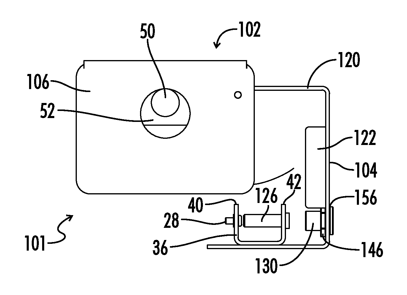
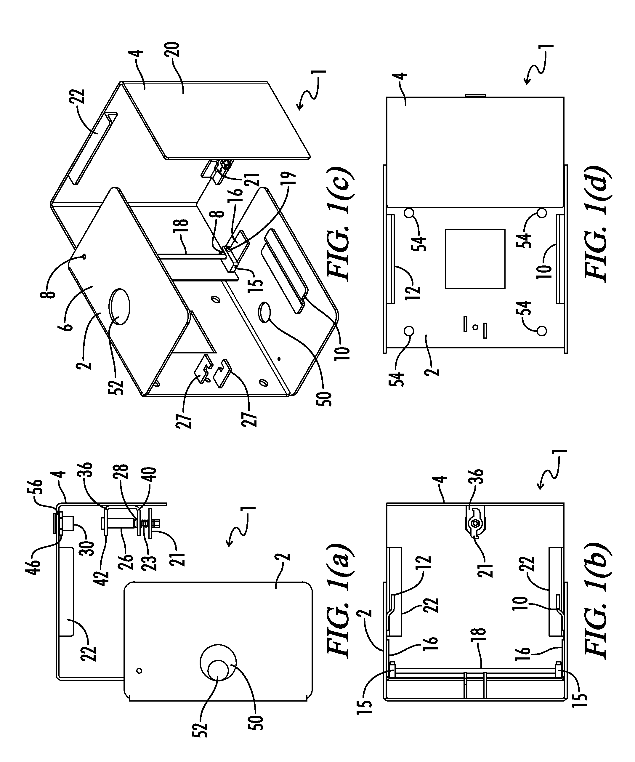
[0039]FIGS. 1(a-d) are top (a), isometric (b), side (c) and front views (d) of a preferred embodiment 1 of the present invention. The unique locking mechanisms and robust housing of the enclosure 1 shown reduce the risk of authorized access to the contents of the enclosure 1. The preferred embodiment shown in the figures consists of a wrapper assembly 2 and a door assembly 4. The wrapper assembly 2 includes a wrapper housing 6 and the door assembly 4 includes a door housing 20 which serve to mount the components of the assemblies 2 and 4 and protect the contents of the enclosure 1. The wrapper housing 6 and the door housing 20 are preferably constructed from stainless steel.

[0040]The door assembly 4 is pivotally connected to the wrapper assembly 2 with the pivotal attachment consisting of a pin 18 having two ends 8 affixed to the wrapper assembly 2 and a pair of hinge blocks 15 attached to the top and bottom of the door assembly. The hinge blocks 15 have slots that are dimensioned t...


PUM


Abstract

A theft deterrent enclosure that eliminates unauthorized access is disclosed. The enclosure includes a door assembly having three sides and a wrapper assembly having three sides that mate to form a lockable enclosure. A key lock cylinder is mounted in a lock opening of the door assembly such that it blocks the lock opening in a locked position. A keyed interface operates a fastener, such as a compression latch, threaded coupling or lock plate, which is mounted on the door assembly such that the fastener secures the door assembly and the wrapper assembly in a closed position. The keyed interface is positioned on an interior side of the enclosure that is opposite and aligned with the lock opening. A guide sleeve is positioned inside the enclosure that guides a security keyed tool inserted through the lock opening toward the keyed interface. The theft deterrent enclosure can only be opened from a locked position by engaging the key lock cylinder with a key, removing the key lock cylinder tumbler, inserting the security keyed tool adapted to engage the keyed interface through the lock opening and disengaging the fastener.

Description

[0001]This is a Utility Patent Application filed for the invention by Johnny Edward Walker for a “Theft Deterrent Enclosure” that claims priority from U.S. Provisional Patent Application Ser. No. 61 / 180,148 filed May 21, 2009.BACKGROUND OF THE INVENTION[0002]1. Field of the Invention[0003]The present invention relates generally to a new and improved tamper resistant enclosure. More particularly, this invention provides an enclosure for a cable service box that is easy for to service personnel to open and service but resistant to unauthorized access.[0004]2. Description of the Prior Art[0005]Prior art enclosures for protecting cable boxes and telephone lines have proven deficient in a number of respects. Cable television providers currently face many problems with the theft of components and other cable equipment that are mounted in open areas. In some areas, the theft of these types of components such as power supply boxes is a multi-million dollar industry. Cable providers face eve...

Claims


Application Information

Patent Timeline
Patent Type & Authority Patents(United States)
IPC IPC(8): B65D55/14
CPCE05B17/142E05C5/04Y10T70/50Y10T70/5031Y10T70/5367Y10T70/554Y10T70/5544Y10T70/5549Y10T70/7661Y10T70/7955Y10T70/7977
Inventor WALKER, JOHNNY EDWARD
Owner WALKER JOHNNY EDWARD
Why Eureka
Try Eureka