Rotary piston engine

a rotary piston and engine technology, applied in the direction of rotary piston engines, rotary or oscillating piston engines, arcuate-engagement engines, etc., can solve the problem of low stress on individual joints, and achieve the effect of simple gear mechanism and compact design

Inactive Publication Date: 2012-10-30
KUROWSKI WALDEMAR
View PDF43 Cites 5 Cited by
  • Summary
  • Abstract
  • Description
  • Claims
  • Application Information

AI Technical Summary

Benefits of technology

[0007]The invention is intended to provide a rotary piston engine characterized by a compact design and by a comparatively simple gear mechanism.

Problems solved by technology

This results in low stresses on the individual joints and above all in low peak forces occurring in these joints.

Method used


Image

  • Rotary piston engine
  • Rotary piston engine
  • Rotary piston engine

Examples


Embodiment Construction

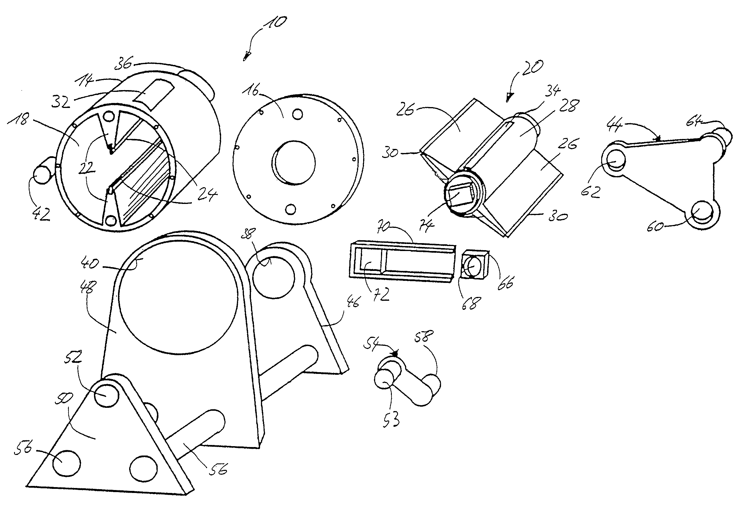
[0028]The representations of FIGS. 2a and 2b show a rotary piston engine in accordance with the invention and in accordance with a first embodiment of the invention. With regard to the schematic representation in FIG. 2a, it must be borne in mind that there the individual elements are drawn inside one another as a wire frame model, so that lines which are not discernable to the beholder are also shown. It can be seen that the rotary piston engine has a cylinder liner 10 that is received rotatably in a frame 12. The cylinder liner 10 comprises a cup-like section 14 and a cover plate 16 which in the assembled state closes off a working space 18 inside the cylinder liner 10. Inside the cylinder liner 10 and concentric thereto, a rotor 20 is held that is mounted rotatably relative to the cylinder liner 10. The cylinder liner 10 has two approximately wedge-shaped ribs 22 opposite to one another that extend from an all-round wall of the cylinder liner 10 in the direction of its central lo...


PUM


Abstract

A rotary piston engine with a frame, a cylinder liner mounted rotatably therein, a rotor mounted coaxially in the cylinder liner and a gear mechanism connecting the frame, the liner and the rotor, where the gear mechanism is outside a working space arranged between liner and rotor and where the gear mechanism couples the cylinder liner and the rotor for a relative movement periodically oscillating between positive and negative rotational speed. The gear mechanism and the liner form with the rotor a transmission with five rotational joints with a degree of freedom of one and one rotational/prismatic joint, where the gear mechanism has a rotational element mounted rotatably by a first rotational joint on the frame and a connecting rod connected rotatably by a second rotational joint to the rotational element and rotatably by a third rotational joint to the cylinder liner and by the rotational/prismatic joint to the rotor.

Description

FIELD OF THE INVENTION[0001]The invention relates to a rotary piston engine with a frame, a cylinder liner mounted rotatably in the frame, a rotor mounted coaxially in the cylinder liner and a gear mechanism connecting the frame, the cylinder liner and the rotor, where the gear mechanism is arranged outside a working space defined between cylinder liner and rotor and where the gear mechanism couples the cylinder liner and the rotor so that the rotor periodically leads and lags relative to the cylinder liner.BACKGROUND OF THE INVENTION[0002]Generic rotary piston engines are known for example from German patent specification DE 27432. A gear mechanism having several connecting rods acts here on two shafts running into one another, one of which is connected to the rotor and the other to the cylinder liner. The gear mechanism has a total of seven rotational joints, i.e. the mounting of the central shaft inside the hollow shaft, the mounting of the hollow shaft inside the frame and two c...

Claims


Application Information

Patent Timeline
Patent Type & Authority Patents(United States)
IPC IPC(8): F02B53/00F01C1/00F01C1/07F01C1/077F04C18/00F04C2/00
CPCF01C1/07F01C1/077
Inventor KUROWSKI, WALDEMAR
Owner KUROWSKI WALDEMAR
Why Eureka
Try Eureka