
Releasing control unit for a residential fire protection system

a control unit and residential technology, applied in fire rescue, dental surgery, medical science, etc., can solve the problems of drying sprinkler system being slower to respond to fire conditions, unable to provide any indication of how to determine hydraulic demand, and water delivery time, etc., to facilitate detector 46 operation and facilitate water delivery

Active Publication Date: 2012-10-30
TYCO FIRE PRODS LP
View PDF29 Cites 12 Cited by
  • Summary
  • Abstract
  • Description
  • Claims
  • Application Information

AI Technical Summary

Problems solved by technology

By its nature, a dry sprinkler system is slower to respond to fire conditions than a wet system because the dry gas must first be exhausted from the system before the fire-fighting liquid is expelled from the fire sprinkler.
Such delay creates a “water delivery time” to the sprinkler.
For example, NFPA Standard 13 (2002) fails to specify any criteria in a design of a dry pipe residential fire sprinkler system, including a hydraulic demand calculation, the quantity of residential fire sprinklers consonant with the hydraulic demand calculation or installation constraints and use of residential fire sprinklers in a dry pipe fire protection system.
While these standards may have considered a residential piping system other than a wet pipe system, e.g., a dry pipe residential system, the standards do not provide any indication of how to determine a hydraulic demand as part of a design of such systems.
In addition to the failure of the NFPA and UL Standards to provide any direction on a hydraulic design calculation for a dry type residential sprinkler system, these Standards also fail to provide any guidance on how a dry type residential fire sprinkler protection system design would be controlled and monitored in residential applications.
Thus, the design methodologies, installation requirements, and control of a fire protection system in residential applications with residential fire sprinklers, other than a wet pipe system, are believed to be notably lacking.

Method used


Image

  • Releasing control unit for a residential fire protection system
  • Releasing control unit for a residential fire protection system
  • Releasing control unit for a residential fire protection system

Examples


Embodiment Construction

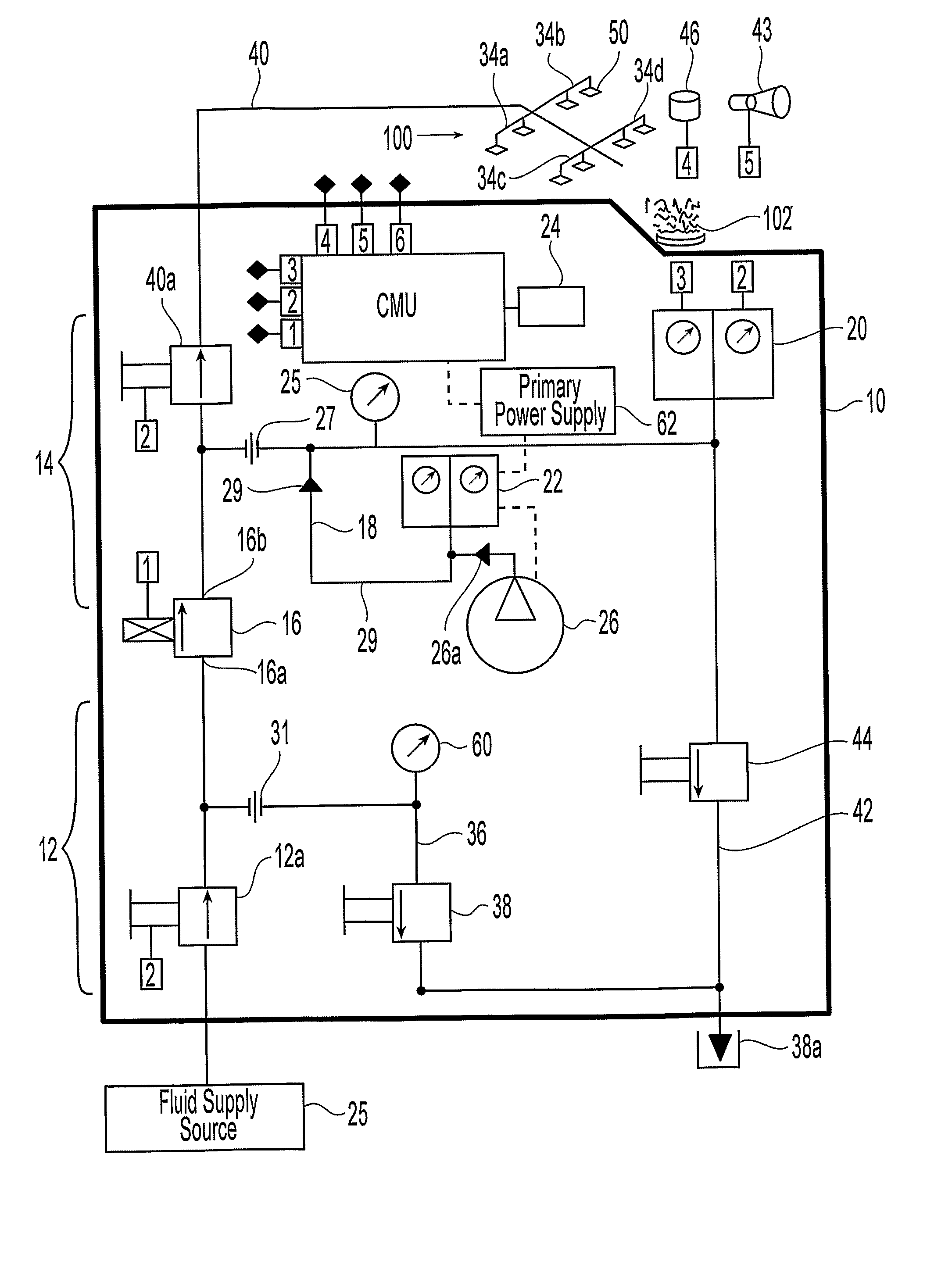
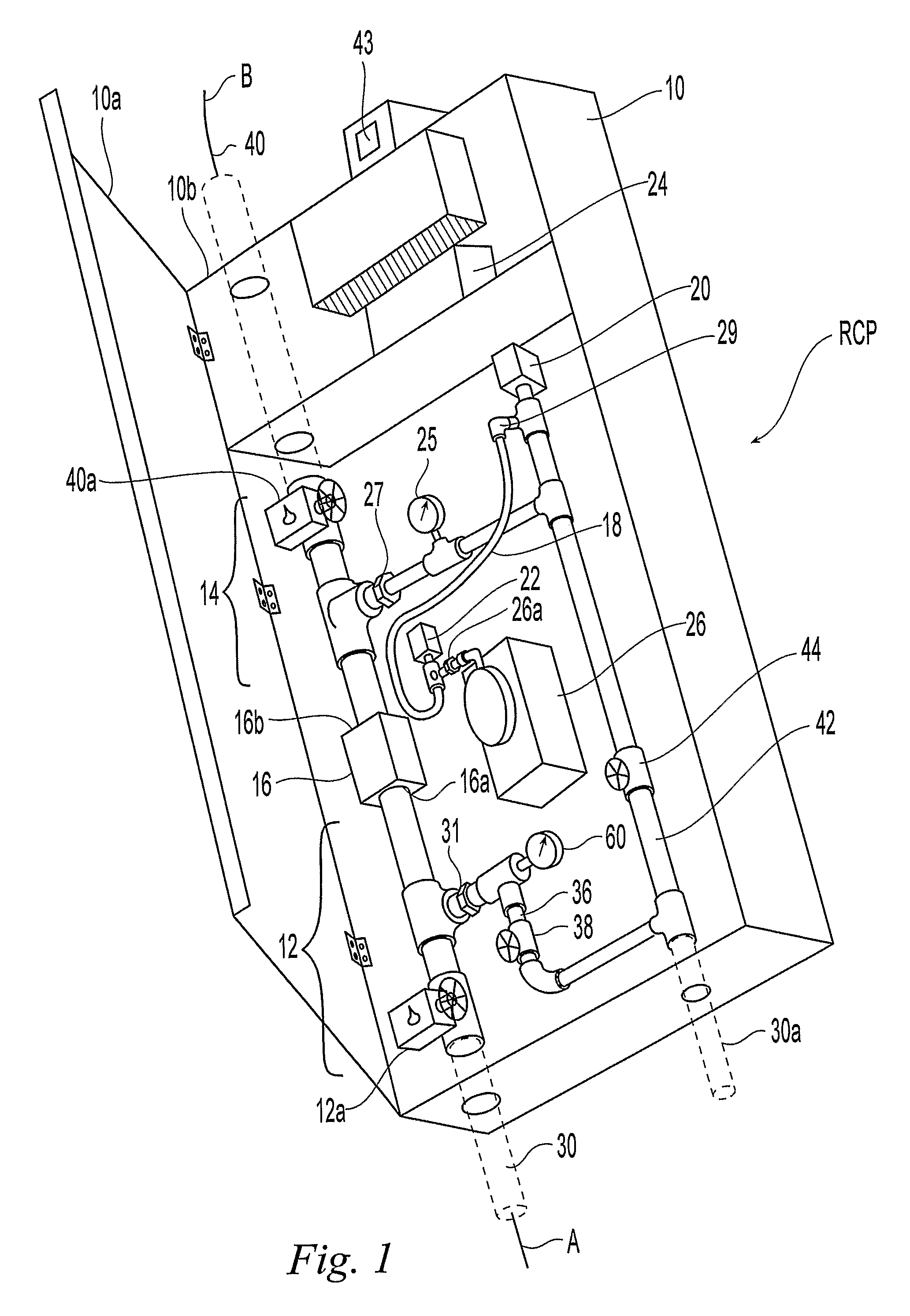
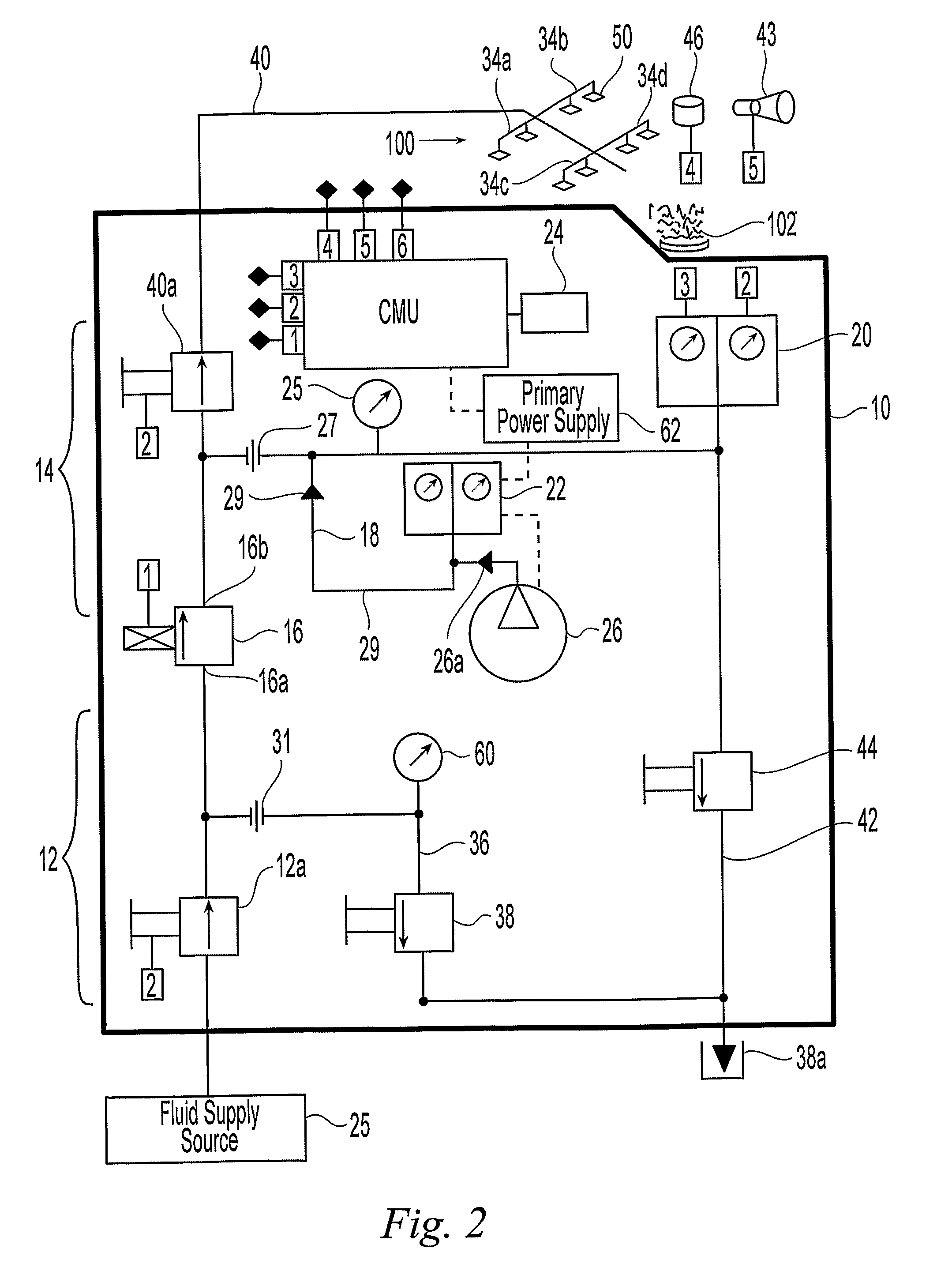
[0037]FIGS. 1 and 2 illustrate the preferred embodiments. In particular, FIG. 1 illustrates a releasing control panel (“RCP”) for a fire protection system 100 in a residential application. As used herein, the term “residential” indicates a dwelling unit as defined in the 2002 Edition of the NFPA Standard 13, and similarly in the 2002 Edition of NFPA 13D and 13R, which can include commercial dwelling units (e.g., rental apartments, lodging and rooming houses, board and care facilities, hospitals, motels or hotels), to indicate one or more rooms, arranged for the use of individuals living together, as in a single housekeeping unit, that normally has cooking, living, sanitary, and sleeping facilities. The dwelling unit normally includes a plurality of compartments as defined in NFPA Standard 13, where generally each compartment is a space that is enclosed by walls and ceiling. The standards relating to residential fire protection, as promulgated by the National Fire Protection Associat...


PUM


Abstract

A releasing control panel (RCP) for use with residential fire protection systems and methods. The RCP provides a primary communication between a liquid supply source and a network of pipes and sprinklers using a series of three control valves. The RCP also encloses a pressure source providing pressurized gas to an auxiliary line that is isolated from the pipe network and sprinklers, with pressurized gas being provided in response to a pressure in the isolated auxiliary line. The RCP also encloses a secondary communication between the series of the control valves and a drain without the use of a bypass system for the primary communication. The RCP further encloses a power supply and a controller that communications with a fire detector disposed in a dwelling at a defined spacing to a sprinkler.

Description

PRIORITY DATA AND INCORPORATION BY REFERENCE[0001]This application is a 35 U.S.C. 371 application of PCT / US2006 / 021683, filed Jun. 5, 2006, which claims priority to U.S. Provisional Patent Application Ser. No. 60 / 687,656, filed Jun. 3, 2005, the entireties of which are hereby incorporated by reference.TECHNICAL FIELD[0002]This invention relates generally to the residential sprinkler system controls. More specifically, the present invention provides a releasing control panel for controlling the release of a fire fighting fluid into a network of pipes of a residential sprinkler system.BACKGROUND OF THE INVENTION[0003]An automatic sprinkler system is one of the most widely used devices for fire protection. These systems have sprinklers that are activated once the ambient temperature in an environment, such as a room or a building, exceeds a predetermined value. Once activated, the sprinklers distribute fire-extinguishing fluid, preferably water, in the room or building. A fire sprinkle...

Claims


Application Information

Patent Timeline
Patent Type & Authority Patents(United States)
IPC IPC(8): A62C35/00A62C37/36A62C37/10A62C3/06A62C2/00
CPCA62C35/645A62C37/44A62C35/62A62C35/68
Inventor WILKINS, ROGER S.GOLINVEAUX, JAMES E.FESSENDEN, MARK E.
Owner TYCO FIRE PRODS LP
Learn More