Glass run

a glass run and run technology, applied in the field of glass runs, can solve the problems of b>8/b> complicating the structure, and achieve the effects of softening the impact, reducing the generation of the impact sound (bumping sound), and reducing the generation of the impact sound

Active Publication Date: 2012-10-30
NISHIKAWA RUBBER
View PDF13 Cites 3 Cited by
  • Summary
  • Abstract
  • Description
  • Claims
  • Application Information

AI Technical Summary

Benefits of technology

[0021]Such a structure softens the impact at the time of the bumping the door glass, thereby reducing generation of the impact sound (bumping sound).
[0024]According to the glass run according to the second aspect of the present invention, the connecting wall has the lip formed on the inner surface on the inner-cabin side thereof, which slants toward the outer-cabin side wall so that the lip makes the elastic contact with the door glass and the lip is pressed against the connecting wall. Such a structure softens the impact generated by bumping the door glass compared with a glass run without the lip formed therein.
[0025]According to the glass run according to the third to fifth aspects of the present invention, the space has the buffer member provided therein, an example of which is the soft sponge. Accordingly, generation of the impact sound (bumping sound) is further reduced compared with a glass run without the buffer member provided therein.
[0026]Especially, according to the glass run according to the fifth aspects of the present invention, the buffer member is provided in the space of the mounted glass run in such a manner that before the door glass abuts the connecting wall, the buffer member is in the non-compressed state where the buffer member is slightly brought into contact with the door sash or the door frame and is not compressed. Accordingly, when the door glass abuts the connecting wall, the largest compression amount of the buffer member softens the impact.

Problems solved by technology

In addition, there also remains a problem that formation of the convexes 13 and the concaves 14 on the outer surface of the connecting wall 8 complicates the structure.

Method used


Image

  • Glass run
  • Glass run
  • Glass run

Examples


Embodiment Construction

[0036]Referring to drawings, embodiments of the present invention will be described. When constituents or items correspond to those in prior arts, the same symbols are used.

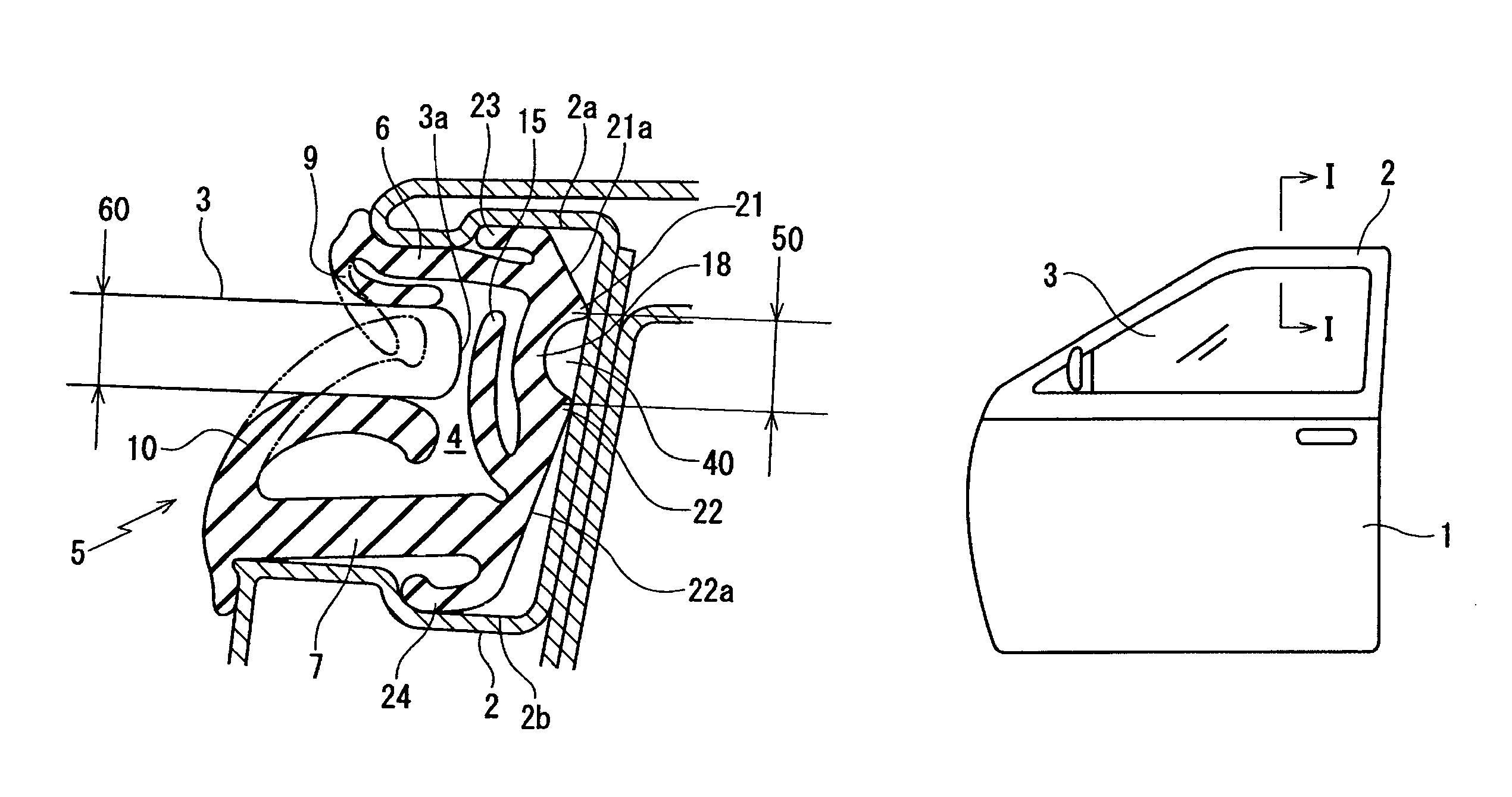
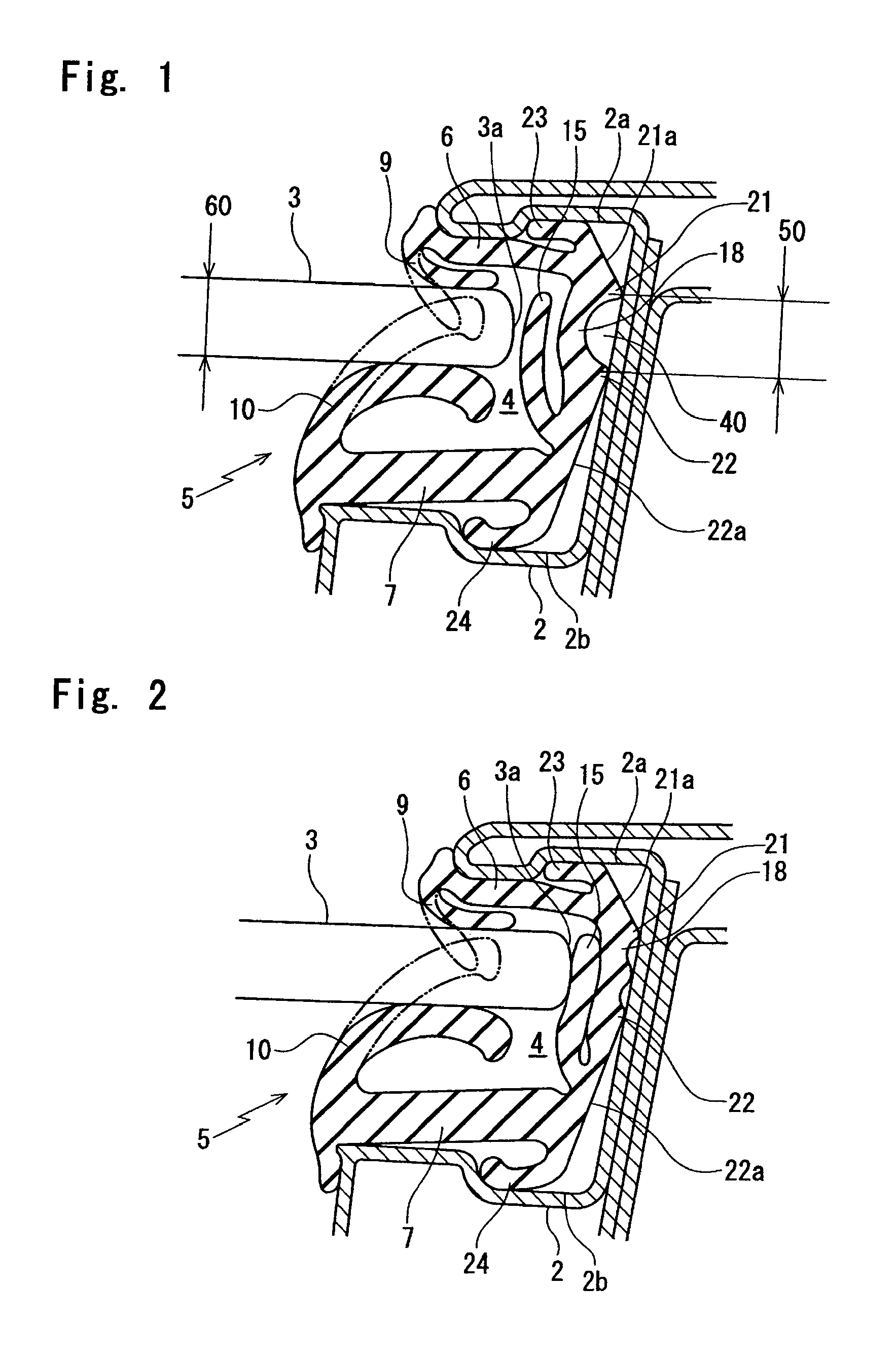
[0037]FIG. 1 is an enlarged cross section of a glass run according to an embodiment of the present invention and corresponds to a I-I line enlarged cross section of FIG. 6. FIG. 2 is a cross section of the glass run of FIG. 1 at a time of fully closing a door glass.

[0038]In the same manner as the prior arts, a glass run 5 according to an embodiment of the present invention is fit on a door sash 2 (or a door frame) of an automobile door 1 and guides a door glass 3 lifting or lowering into a ditch part 4.

[0039]The glass run 5 has a cross-section roughly U-shape comprising: two side walls, an outer-cabin side wall 6 and an inner-cabin side wall 7; and a connecting wall 18 which connects the outer-cabin side wall 6 and the inner-cabin side wall 7. The outer-cabin side wall 6 has an outer lip 9 formed on an inner-cabi...


PUM


Abstract

A glass run 5 fit on a door sash 2 of an automobile has: a cross-section roughly U-shape comprising an outer-cabin side wall 6, an inner-cabin side wall 7 and a connecting wall 18 which connects the outer-cabin side wall 6 and the inner-cabin side wall 7 for guiding a door glass 3 lifting or lowering into a ditch part 4; and an outer lip 9 and an inner lip 10 respectively formed on inner surfaces of both of the side walls 6, 7, which extend toward a connecting wall 18 side and are slidably brought into contact with the door glass 3, wherein: the connecting wall 18 has a part thereof swelled and curved toward an inner surface side thereof, which faces a position on the connecting wall 18 where the door glass 3 collides; the connecting wall 18 swelled and curved has two projections 21, 22 formed on an outer surface thereof, which come into contact with the door sash 2 and of which an interval 50 therebetween is not more than thickness 60 of the door glass 3; and a position surrounded by the two projections 21, 22, the connecting wall 18 and the door sash 2 is formed into a space 40 having a cross-section roughly semicylindrical shape.

Description

BACKGROUND OF THE INVENTION[0001]The present invention relates to a glass run which is fit on a door sash or a door frame of an automobile and guides a door glass lifting or lowering.[0002]As shown in FIGS. 6 and 7, an ordinary glass run 5 for guiding a door glass 3 lifting or lowering into a ditch part 4 has been fit on a door sash 2 of an automobile door 1. FIG. 7 is a I-I line enlarged cross section of FIG. 6.[0003]The glass run 5 has a cross-section roughly U-shape having the ditch part 4 formed therein, which comprises two side walls, an outer-cabin side wall 6 and an inner-cabin side wall 7, and a connecting wall 8 which connects the outer-cabin side wall 6 and the inner-cabin side wall 7. The outer-cabin side wall 6 has an outer lip 9 formed on an inner-cabin side as an inner surface thereof, which extends toward a connecting wall 8 side. In the same way, the inner-cabin side wall 7 has an inner lip 10 formed on an outer-cabin side as an inner surface thereof, which extends t...

Claims


Application Information

Patent Timeline
Patent Type & Authority Patents(United States)
IPC IPC(8): B60J10/04
CPCB60J1/08
Inventor SATO, NOBUMASAKISHI, KOTAROMIYAHARA, HIROAKI
Owner NISHIKAWA RUBBER
Why Eureka
Try Eureka