Sterilizable platform with configurable frame and method of constructing

a technology of configurable frames and platforms, applied in the direction of dismountable cabinets, girders, furniture parts, etc., can solve the problems of debris or material trapped on the surface of the device, and achieve the effects of reducing facilitating sterile cleaning, and eliminating the need to remove connected parts

Active Publication Date: 2016-12-13
LAWRENCE STEVEN
View PDF7 Cites 3 Cited by
  • Summary
  • Abstract
  • Description
  • Claims
  • Application Information

AI Technical Summary

Benefits of technology

[0018]Every protrusion that extends from the surface of a component should be a continuous piece of the material forming the component. That protrusion extending from the surface edge of the component may be bent at an angle to serve a particular secondary purpose such as providing additional support or softening contact. In any case, no additional welding is necessary with regards to support protrusions or tabs. Said tabs located at the bottom of a component serving as a table leg may be bent to provide a smooth rounded surface to soften impact on the floor surface. This is an acceptable substitute for padding typically glued or screwed onto the bottom of a table leg to minimize scuffing of floor surfaces. Alternatively, the protrusions or tabs may extend upward from a horizontal frame to hold material inward within the constructed support frame device.

Problems solved by technology

There is no surface on this device where debris or material may be trapped, requiring manual cleaning.

Method used


Image

  • Sterilizable platform with configurable frame and method of constructing
  • Sterilizable platform with configurable frame and method of constructing
  • Sterilizable platform with configurable frame and method of constructing

Examples


Embodiment Construction

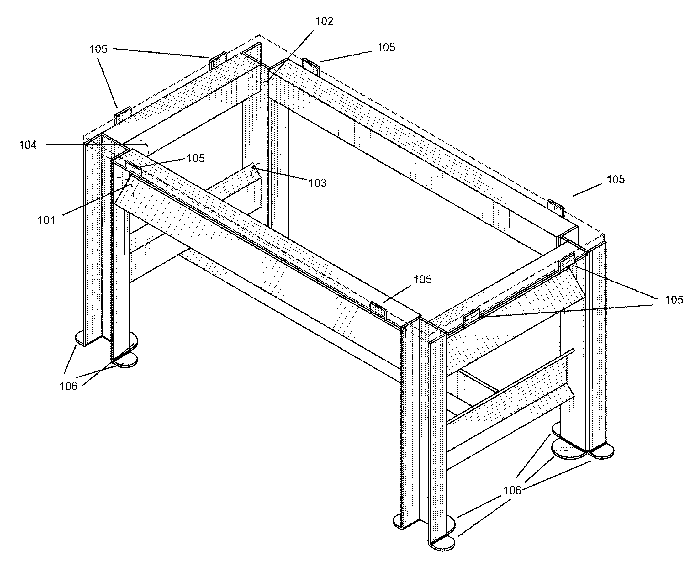
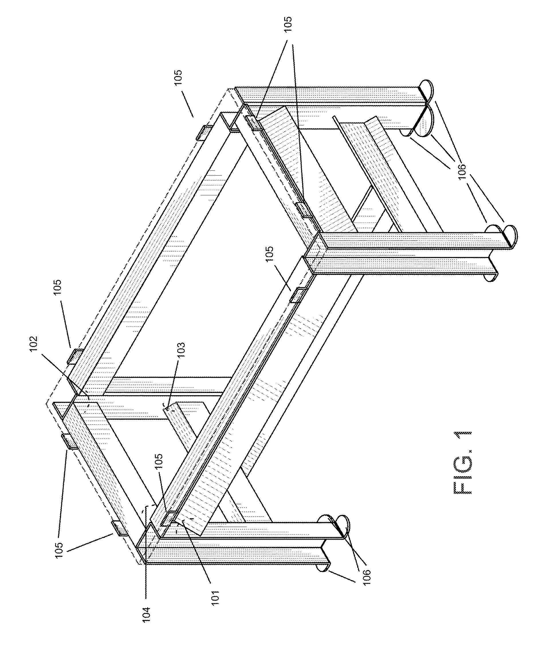
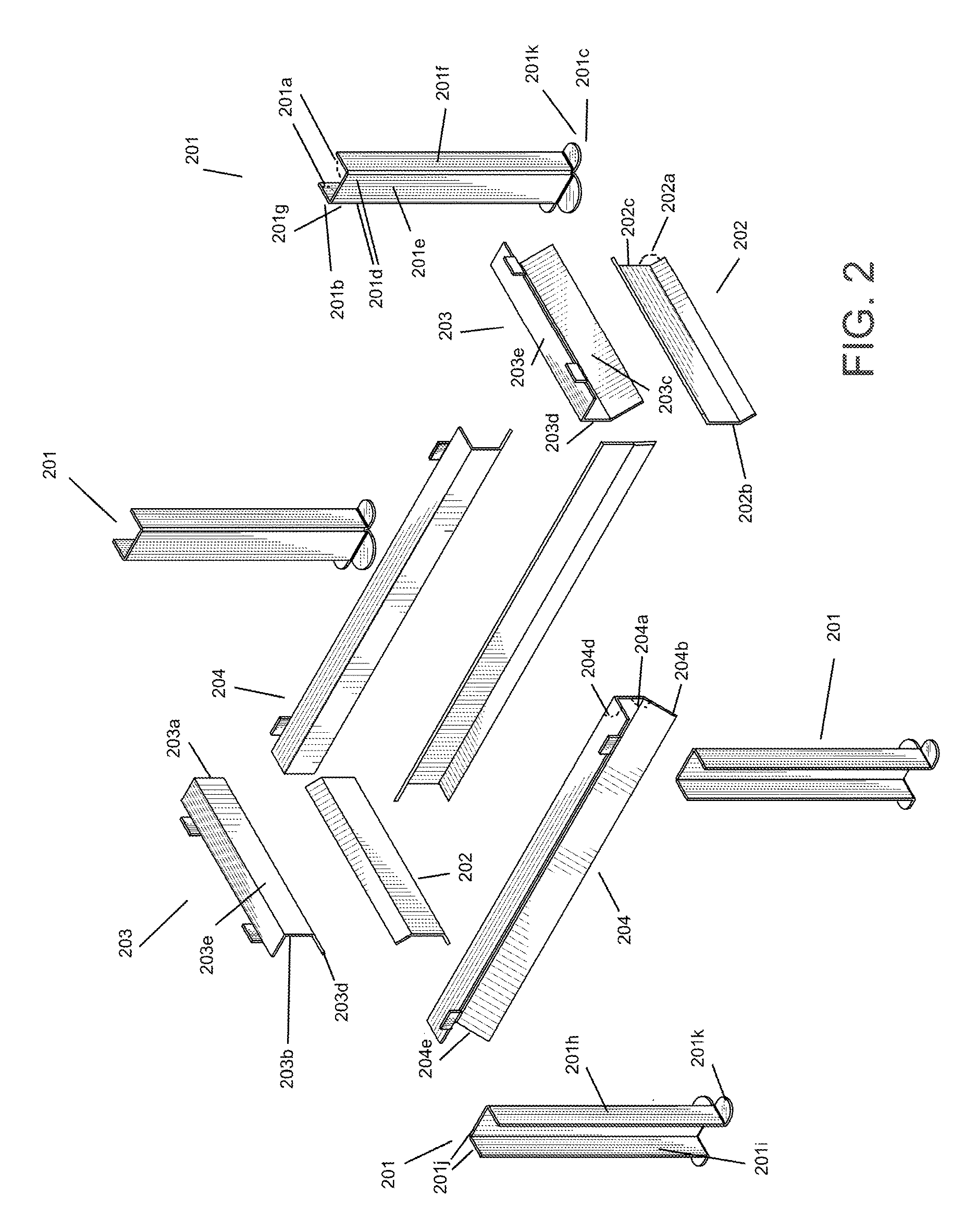
[0020]Each component (FIG. 2, 201, 202, 203, 204; FIG. 4, 401, 402, 403) comprising solid sterilizable material, preferably made of durable stainless metallic material that may be bent and welded. Each said component further having a length, a width, a thickness, and a cross sectional shape. Said cross sectional shape is preferably unchanged throughout the length of each individual said component. Said cross sectional shape of each individual said component having one or more bent angles (FIG. 2, 201a, 202a, 204a; FIG. 4, 401a, 401b, 402a). Each individual of said one or more bent angles comprising any one or more of the following angles of bending: 180 degree, 135 degree, 90 degree or 45 degree angles. Each said component having two or more ends (FIG. 2, 201b, 201c, 202b, 202c, 203a, 203b, 204b, 204e). Each said end being cut at either a 45, 90 or 135 degree angle (FIG. 2, 201d, 204d; FIG. 4, 401b, 401c) to enable welding against the surface of another component to create an open s...


PUM

PropertyMeasurementUnit
angleaaaaaaaaaa
angleaaaaaaaaaa
cross sectional angleaaaaaaaaaa

Abstract

A free standing self sterilizable device and method of construction by connecting together a plurality of connected individual modular components. The individual modular components are provided in such manner to enable multiple configurations in frame structure shape when assembled. The device is self sterilizing by its material composition, its open smooth surface and its downward or horizontal slanting surfaces. The device herein is intended for use in the food or medical industry.

Description

FEDERALLY SPONSORED RESEARCH OR DEVELOPMENT[0001]Not applicable.REFERENCE TO SEQUENCE LISTING, A TABLE, OR A COMPUTER LISTING APPENDIX[0002]Not applicable.CROSS REFERENCE[0003]This non-provisional utility patent application incorporates by reference the earlier filed provisional patent application, Application No. 61 / 994,639, in its entirety. This non-provisional patent application claims benefit of said copending provisional patent application, effectively filed on May 16, 2014, pursuant to 35 U.S.C. 119(e) and 37 C.F.R. 1.78 (a)(4)-(a)(6) and all other relevant sections of the law not referred to herein.COPYRIGHT NOTICE[0004]A portion of the disclosure of this patent document contains material that is subject to copyright protection. The copyright owner has no objection to the facsimile reproduction by anyone of the patent document or patent disclosure as it appears in the Patent and Trademark office, patent file or records, but otherwise reserves all copyright rights whatsoever.B...

Claims


Application Information

Patent Timeline
Patent Type & Authority Patents(United States)
IPC IPC(8): A47B47/04B21D47/04C12C13/10A47B13/06C12C11/00E04B1/24E04C3/04B01L9/02A47B37/00A61B17/00A47B7/00
CPCA47B13/06A47B47/047A61B50/10A61B50/15C12C11/006C12C13/10B21D47/04A47B7/00A47B2037/005A61B2017/00526B01L9/02E04B2001/2415E04B2001/2472E04C2003/0413Y10T403/479A47J31/20A47J31/0636
Inventor LAWRENCE, STEVEN
Owner LAWRENCE STEVEN
Why Eureka
Try Eureka