Damper mechanism

a technology of adamper and a rotor, which is applied in the direction of mechanical actuated clutches, friction linings, couplings, etc., can solve the problems of excessive torque generated at the tires, excessive shaking of the vehicle, and transmission to rattle, etc., and achieve the effect of suppressing the enlargement of the prescribed angl

Inactive Publication Date: 2005-02-22
EXEDY CORP
View PDF9 Cites 3 Cited by
  • Summary
  • Abstract
  • Description
  • Claims
  • Application Information

AI Technical Summary

Benefits of technology

An object of the present invention is to suppress the enlargement of the prescribed angle in a damper mechanism that is configured not to allow a friction mechanism to operate within a prescribed angular range.
A damper mechanism described in accordance with a preferred embodiment of the present invention has a first rotary member, a second rotary member, a damper section, a friction mechanism, a friction suppressing mechanism, and an elastic member. The second rotary member is arranged such that it can rotate relative to the first rotary member. The damper section elastically couples the first rotary member and the second rotary member together in a rotational direction. The friction mechanism can generate friction when the first rotary member and the second rotary member rotate relative to each other. The friction suppressing mechanism is configured to prevent the friction mechanism from operating within a prescribed angular range. The elastic member softens the impact between members that touch each other at the end of the prescribed angle. With this damper mechanism, the members can strike against each other at the ends of the prescribed angular range due to engine combustion fluctuations because the frictional mechanism does not operate within the prescribed angular range due to the elastic members. However, since the elastic members soften the impact between the members that contact each other, wearing of the members is reduced and enlargement of the prescribed angular range is suppressed.
A damper mechanism in accordance with a third aspect of the present invention is the damper mechanism of the first or second aspect, wherein the friction suppressing mechanism has two members aligned in the rotational direction and the elastic member is disposed rotationally between the two members. With this damper mechanism, the elastic members soften the impact between the two members of friction suppressing mechanism.

Problems solved by technology

For example, while waiting at a traffic light a driver might shift the gear into neutral, causing the transmission to rattle.
If the rigidity of the drive transmission system is low, the torque transmitted to the tires is transmitted back from the tires as torque and a resulting lurching reaction causes excessive torque to be generated at the tires.
As a result, longitudinal vibrations occur that shake the vehicle excessively back and forth.
In the case of idling noises the problem lies in the zero torque region of the torsion characteristic of the clutch disk assembly.
Meanwhile, the second stage or high twisting angle region of the torsion characteristic has a relatively high torsional rigidity and high hysteresis torque.
The damper mechanism is configured to have a low hysteresis torque in the second stage of the torsion characteristic and does not allow a large friction mechanism of the second stage to operate when small vibrations are inputted due to such factors as combustion fluctuations in the engine.
The damper mechanism does not allow the large friction mechanism of the second stage to operate within a prescribed angular range in the second stage of the torsion characteristic.
However, since the frictional resistance is small within the gap, variations in the rotational speed of the engine cause the two members to strike constantly against each other and thus be subjected to physical shock.
Consequently, over a long period of use, the two members wear causing the gap to become larger than the original gap setting.
When the gap in which the large friction mechanism of the second stage is not allowed to operate becomes larger, the ability of the mechanism to absorb noise and vibrations declines.

Method used


Image

  • Damper mechanism
  • Damper mechanism
  • Damper mechanism

Examples


Embodiment Construction

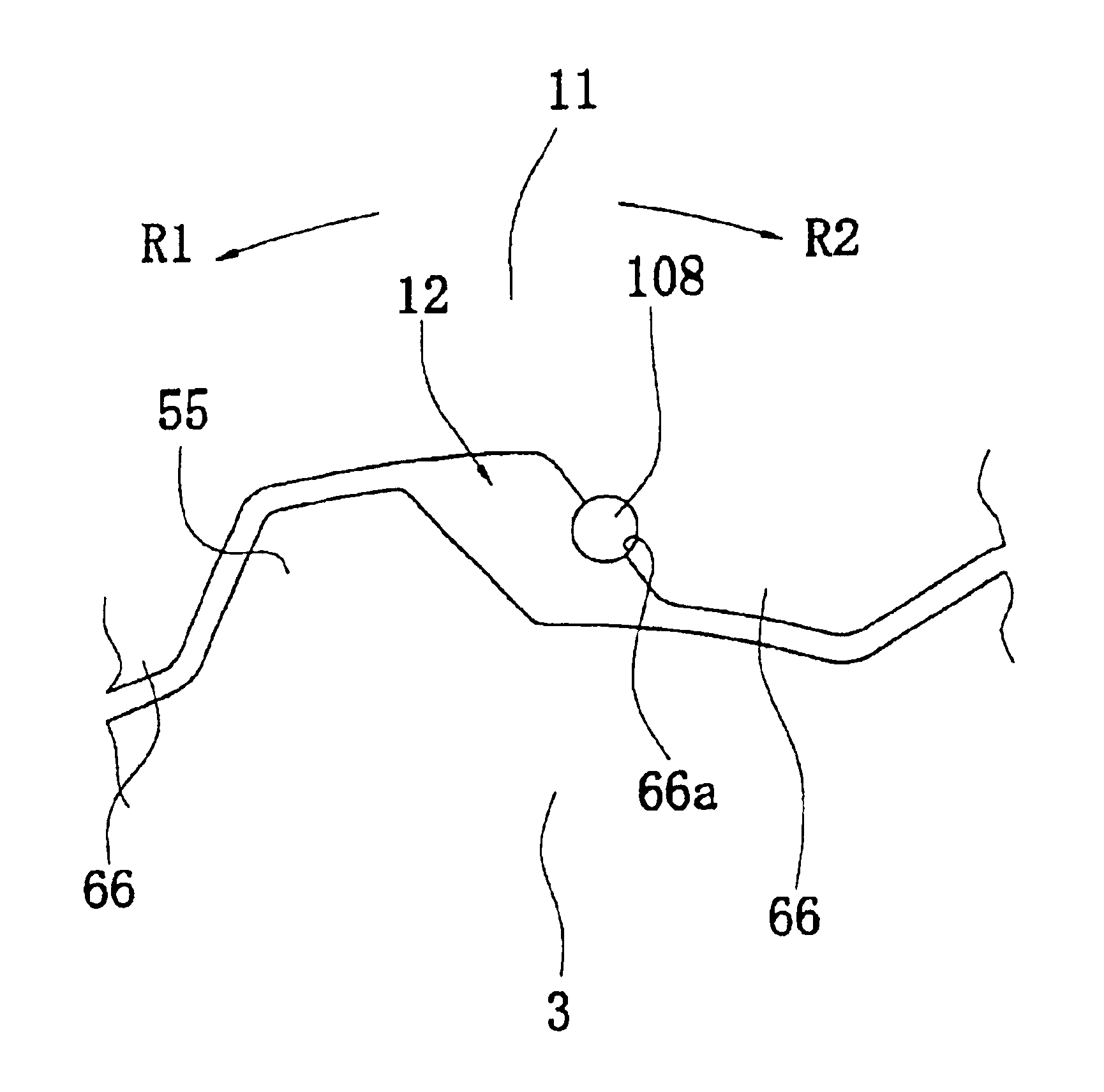
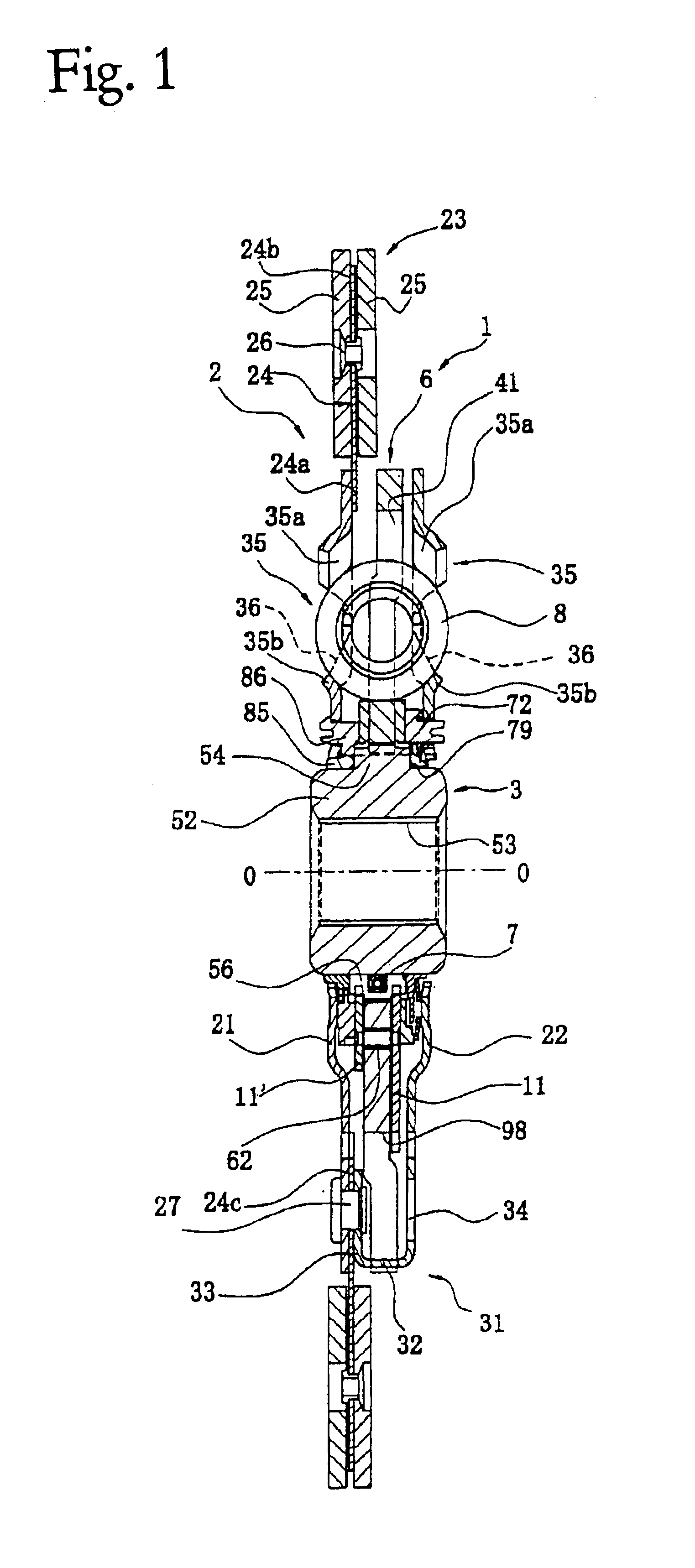
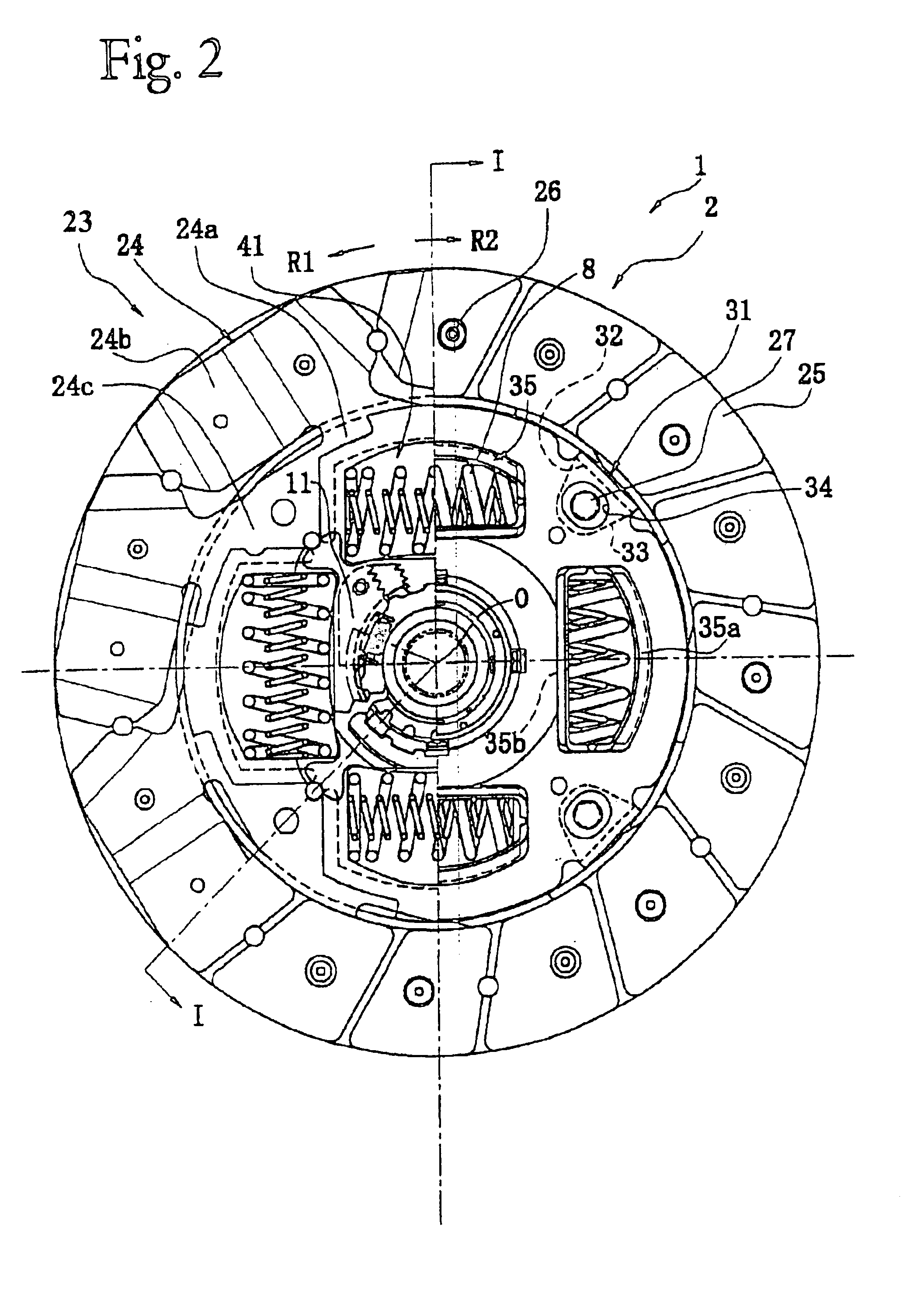
FIG. 1 illustrates a cross-sectional view of a clutch disk assembly 1 in accordance with a preferred embodiment of the present invention. FIG. 2 is an elevational view of the same. The clutch disk assembly 1 is a power transmission device used in the clutch device of a vehicle. The clutch disk assembly 1 has a clutch function and a damper function. The clutch function connects and disconnects torque by engaging and disengaging a flywheel (not shown) of an engine (not shown). The damper function absorbs and damps torque fluctuations that are received from the flywheel side using springs and the like.

Line O—O in FIG. 1 represents a rotational axis, i.e., rotational centerline, of the clutch disk assembly 1. The engine and flywheel (not shown) are disposed to the left of FIG. 1 and the transmission (not shown) is disposed to the right of FIG. 1. In FIG. 2, the R1 direction is the rotational drive direction or positive direction of the clutch disk assembly 1, and the R2 direction is the...


PUM


Abstract

A damper mechanism is provided to suppress the enlargement of a prescribed angle in a damper mechanism. A clutch disk assembly 1 has an input rotary member 2, a spline hub 3, a damper section 4, a large friction mechanism 13, a friction suppressing mechanism, and an elastic member 104. The spline hub 3 is arranged to rotate relative to the input rotary member 2. The damper section 4 couples the input rotary member 2 and the spline hub 3 together rotationally. The large friction mechanism 13 can generate friction when the input rotary member 2 and the spline hub rotate relative to each other. The friction suppressing mechanism is a rotational gap θACp for preventing the large friction mechanism operating within a prescribed angular range. The elastic member 104 softens the impact between the members that touch against each other at the end of the prescribed angular range.

Description

BACKGROUND OF THE INVENTION1. Field of the InventionThe present invention relates to a damper mechanism. More specifically, the present invention relates more particularly to a damper mechanism for damping torsional vibrations in a power transmission system.2. Background InformationClutch disk assemblies used in vehicles function as a clutch for engaging and disengaging a flywheel to facilitate the transfer of torque from an engine. Clutch disk assemblies also function as a damper mechanism for absorbing and damping torsional vibrations from the flywheel. In general, vehicle vibrations include idling-related noises such as rattling sounds, traveling-related noises such as rattling associated with acceleration and deceleration and muffled noises, and tip-in / tip-out or low frequency vibrations. The damper function of the clutch disk assembly is provided ideally to eliminate these noises and vibrations.Idling-related noises are rattling noises that emit from the transmission when the g...

Claims


Application Information

Patent Timeline
Patent Type & Authority Patents(United States)
IPC IPC(8): F16F15/12F16F15/129F16D13/64F16F15/131
CPCF16F15/129F16D13/64
Inventor HASHIMOTO, YASUYUKIMASAKI, MICHITOMOAOKI, TATSUYUKI
Owner EXEDY CORP
Why Eureka
Try Eureka