Method for producing hydrogen peroxide from hydrogen and oxygen

a hydrogen peroxide and oxygen technology, applied in hydrogen peroxide, gas-gas reaction process, pressurized chemical process, etc., can solve the problems of high operating loss of currently practiced commercial process, high operating loss of hydrogen peroxide, and safety hazards of hydrogen peroxid

Inactive Publication Date: 2000-03-28
PRINCETON ADVANCED TECH
View PDF1 Cites 43 Cited by
  • Summary
  • Abstract
  • Description
  • Claims
  • Application Information

AI Technical Summary

Benefits of technology

It is a primary object of the invention to provide a process for the reaction of oxygen and hydrogen which is efficient and safe.

Problems solved by technology

The presence of these organics with oxygen and hydrogen peroxide presents safety hazards from their potential reactions.
This destruction of organics involves high operating losses for the currently practiced commercial process.
The direct process, however, does require careful control of the gaseous mixture of oxygen and hydrogen so that they are always outside the explosive range.
However, the organics can react with oxygen or hydrogen peroxide to render these processes uneconomical.
The '618 patent has the limitation of low conversion of hydrogen peroxide per pass and high equipment costs.
This process is expensive to repressure the reactor with oxygen and doesn't lend itself to continuous processing.
These patents have the drawback of having either low conversion per pass or low volumetric efficiency either of which is uneconomical.
This patent has the disadvantage that the majority of the reactor is in the gas phase in which no hydrogen peroxide is formed.
This reaction system requires considerable capital for the use of the membranes.
In the '242 patent, the ratio of the flow of the aqueous medium to the aggregate flow of the hydrogen and oxygen is such that a gas phase regime of large elongated bubbles may be produced, which, if reacted violently would not be surrounded by sufficient liquid volume to cool the gas mixture, resulting in elevated temperature and pressure which can result in an explosion of the gas mixture.

Method used


Image

  • Method for producing hydrogen peroxide from hydrogen and oxygen
  • Method for producing hydrogen peroxide from hydrogen and oxygen
  • Method for producing hydrogen peroxide from hydrogen and oxygen

Examples


example ii

Batch Semicontinuous Process

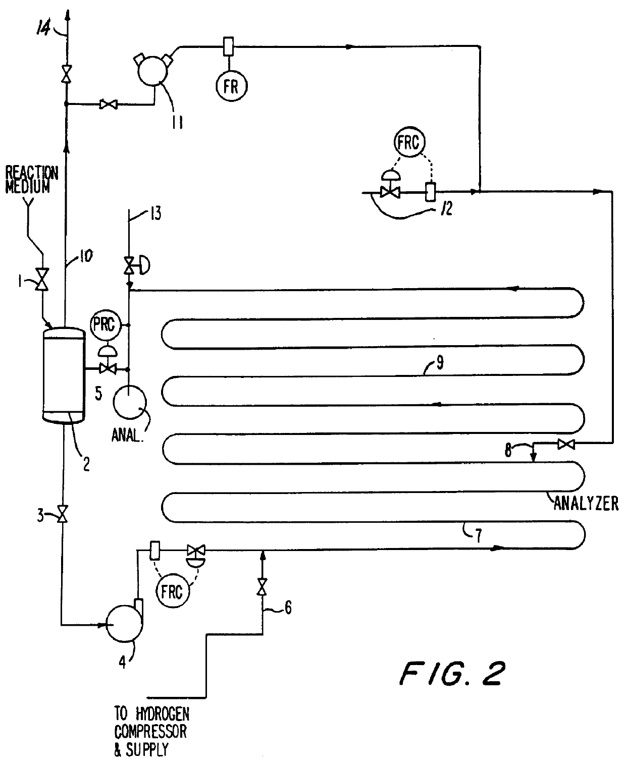
FIG. 2 illustrates an alternate method of operating the process of the invention in a batch, semicontinuous fashion. A fresh batch of reaction medium consisting of a group VIII metal catalyst on an inert support in an acidic aqueous solution, is .charged through valve 1 to separator 2. The solution is charged to the reactor via valve 3 and recirculating pump 4. Once the system is filled, flow of fresh solution is stopped by closing valve 1. The pressure in the system is increased by closing valve 5.

The velocity of the medium is maintained at 10 feet per second or more. Recycle gas is injected before the hydrogen at point 12. Hydrogen is injected at injection system 6. The amount of hydrogen introduced is at or less than the solubility limit in the flowing medium. Oxygen is introduced at point 8, at a sufficient distance downstream (pipe length 7) to ensure the absorption of the bulk of the hydrogen. At full capacity, hydrogen flow is about 15 pounds per h...

example iii

First Modified Batch Semicontinuous Process

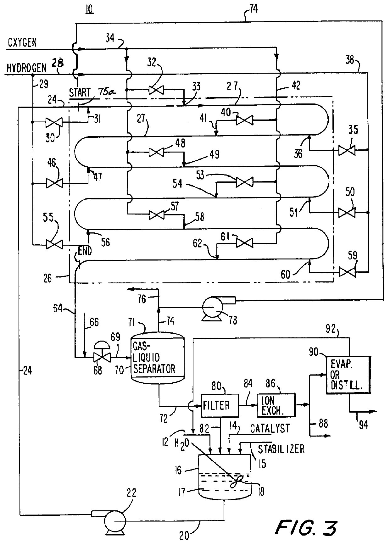
The batch semicontinuous process described in Example II can be carried out in a modified way to reduce both the capital costs and operating costs of the reaction system. The basic flow diagram of FIG. 2 is used with the exception that a second reaction medium pump is provided in parallel with charge pump 4 in order to recirculate the reactor contents at pressure. This latter feature is accomplished by relocating the pressure let down valve 5 from the effluent line from the reactor before the separator to the downstream gas effluent line from the separator 2.

In operation, the operating pressure in the separator remains high (1,000-4,000 psi) throughout the course of the reaction. Pressure is maintained by "head" gas above the separator liquid. The gas to be recycled enters recycle compressor upstream of the pressure letdown valve. The exit gas in line 10 passes through a pressure letdown valve. By configuring the process in this way, any re...

example iv

First Modified Continuous Process

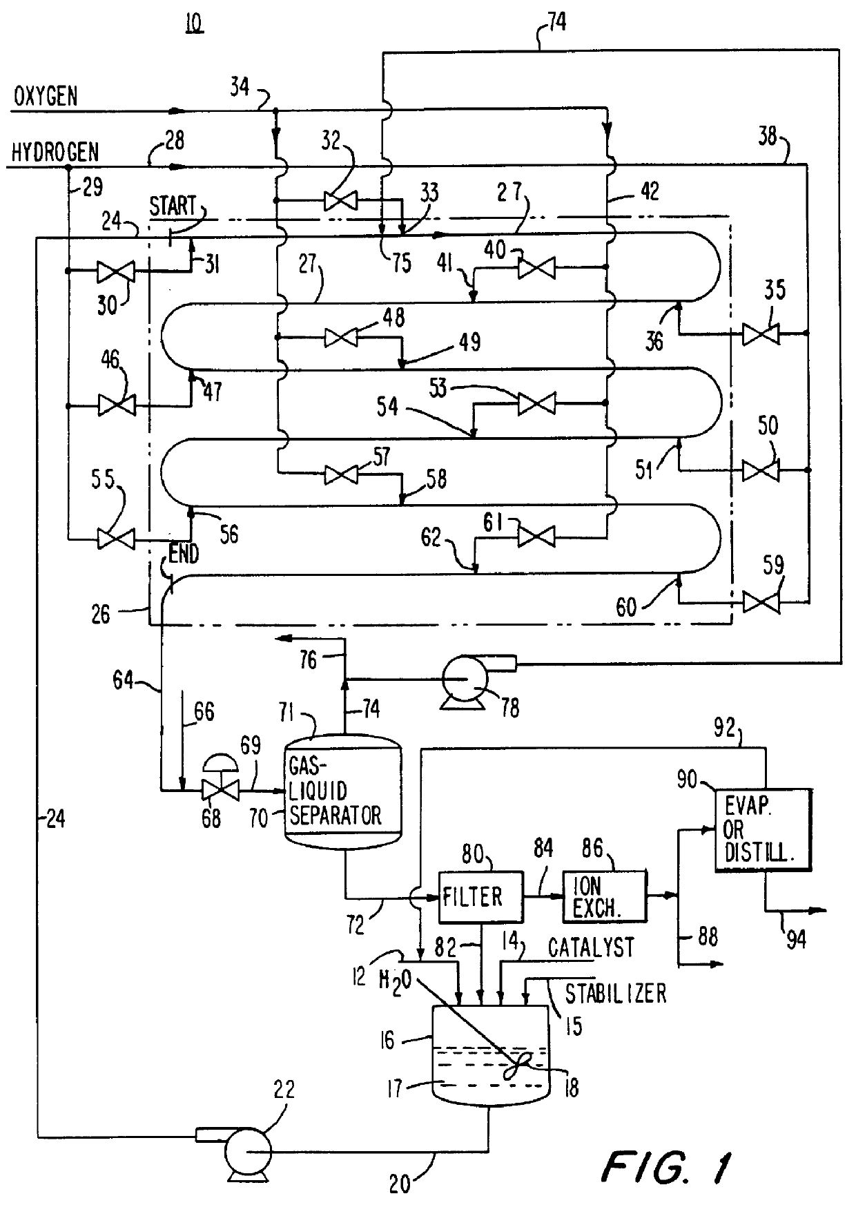
A recirculating aqueous stream of a suspended group VIII metal catalyst deposited on an inert carrier with an acid stabilizer is delivered to the first of two tubular reactors operated in series in the reactor shown in FIG. 1. The reactor consists of vertically oriented 4" schedule 160 pipes 100 feet long, each connected together by 180.degree. U bends. The liquid stream is introduced into the reactor at 15.degree. C.

At the reactor inlet hydrogen gas is injected through a nozzle to form fine individual bubbles in the liquid stream. This produces a bubbly flow regime with a continuous liquid phase and small evenly dispersed individual bubbles. Recycled gas from the gas-liquid separator is injected into the process fluid. This is followed by the injection of oxygen as finely dispersed bubbles which reacts with the hydrogen to form hydrogen peroxide. This is followed by repeated injections for each reactor of first hydrogen and then oxygen to form hydro...


PUM

PropertyMeasurementUnit
velocityaaaaaaaaaa
thicknessaaaaaaaaaa
partial pressureaaaaaaaaaa

Abstract

The invention relates to a method and apparatus for safely producing hydrogen peroxide by injecting dispersed minute bubbles of hydrogen and oxygen into a rapidly flowing liquid medium. The minute bubbles are surrounded by the liquid medium of sufficient volume for preventing an explosive reaction between the hydrogen and oxygen. The liquid medium is formed of an acidic aqueous solution and a Group VIII metal catalyst. Hydrogen is sparged into the flowing medium for dissolution of the hydrogen in the medium. Oxygen bubbles are reacted with the dissolved hydrogen for producing hydrogen peroxide. Preferably, the liquid medium has a velocity of at least 10 feet per second for providing a bubbly flow regime in the reactor. The invention allows the direct combination of oxygen and hydrogen while preventing propagation of an explosive condition within the reactor. The method and apparatus provide for the safe production of hydrogen peroxide with low manufacturing costs.

Description

1. Field of the InventionThe present invention relates to a method and apparatus for producing hydrogen peroxide by injecting minute bubbles of hydrogen and oxygen into a liquid stream of an aqueous solution of water and an inorganic acid and a Group VIII metal catalyst in which the liquid stream flows at high velocity.2. Description of the Related ArtIt is known that a mixture of gaseous oxygen and gaseous hydrogen forms an explosive material. Virtually all currently produced hydrogen peroxide is produced by indirectly combining hydrogen and oxygen. Thus, the primary conventional industrial method for production of hydrogen peroxide uses a chemical agent first for the reduction or hydrogenation. Typically, alkylanthraquinone, such as ethyl or tertiary butyl anthraquinone, is used as the chemical agent. This working solution contains organic solvents such as di-isobutylcarbinol and methyl naphthalene. Oxidation of the intermediate product of the reduction reaction produces hydrogen ...

Claims


Application Information

Patent Timeline
Patent Type & Authority Patents(United States)
IPC IPC(8): B01J8/08B01J19/24B01J8/22B01J8/20B01J3/04B01J12/00B01J10/00C01B15/00C01B15/029C01B15/01
CPCB01J3/044B01J8/08B01J8/228B01J12/00B01J19/0066B01J19/243C01B15/029B01J2219/00094B01J2219/00121B01J2219/00162C01B15/01
Inventor HUCKINS, HAROLD A.
Owner PRINCETON ADVANCED TECH
Why Eureka
Try Eureka