Hollow base decorative surface covering

a decorative surface and hollow base technology, applied in the field of decorative surface coverings, can solve the problems of insufficient anti-skiding force of traditional suctions cups, and wavy mat surfaces which are more difficult for individuals and loads to traverse, so as to increase the amount of frictional drag

Inactive Publication Date: 2012-10-30
GROWLIFE INC
View PDF19 Cites 34 Cited by
  • Summary
  • Abstract
  • Description
  • Claims
  • Application Information

AI Technical Summary

Benefits of technology

[0005]The present invention provides a decorative surface covering comprising at least one decorative layer and a backing layer comprising a patterned array of elastomeric, geometric projections, wherein each geometric projection comprises a concave top surface, an outside wall surface, and an inside wall surface, wherein the inside wall surface defines a hollow area within the projection. When the decorative surface covering is installed over an underlying surface, and pressure is applied to the decorative surface covering, a vacuum is created within the hollow area of the projections and the underlying surface. The vacuum increases the amount of frictional drag between the surface covering and the underlying surface, and thus allows the surface covering to remain in place without the need for an adhesive.

Problems solved by technology

Flooring products must stay in place during use conditions which can include walking forces, dragging forces, rolling load forces, indentation forces, and sub-floor movement due to dimensional instability.
However, none of these have gained much commercial success and there remains a need for resilient decorative surface coverings that do not require adhesives.
While this approach provides acceptable slip-resistance for light shower and bath mat applications, traditional suctions cups are not sufficient to provide sufficient anti-skidding forces to prevent slipping and movement in high traffic and high load areas.
Traditional suction cups also result in a wavy mat surface which is more difficult for individuals and loads to traverse.
The teachings of these patents have not been successfully utilized in traditional flooring products.

Method used


Image

  • Hollow base decorative surface covering
  • Hollow base decorative surface covering
  • Hollow base decorative surface covering

Examples


Embodiment Construction

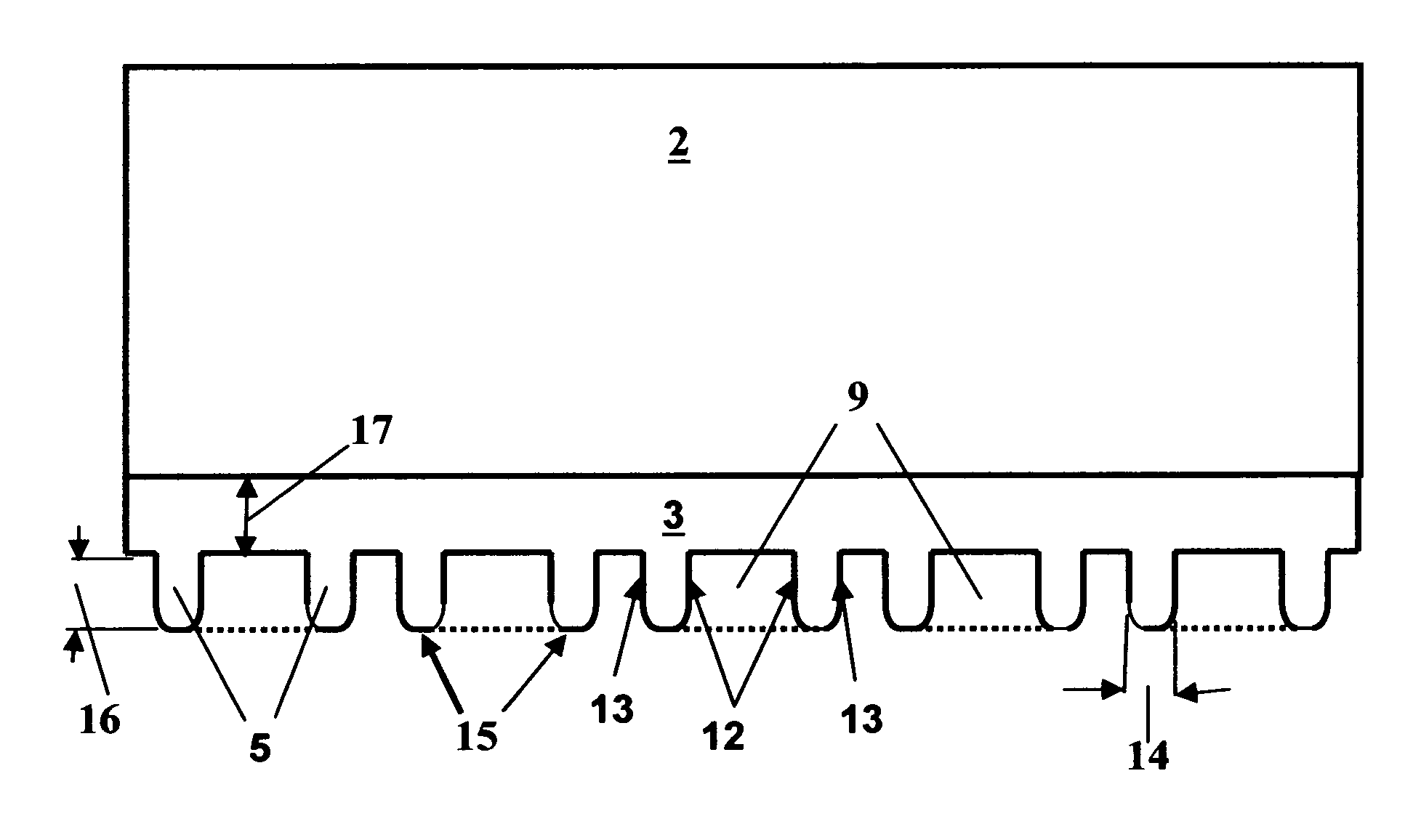
[0018]This invention describes a decorative surface covering comprising at least one decorative layer and a backing layer comprising a patterned array of elastomeric, geometric projections, wherein each geometric projection comprises a concave exposed surface, an outside wall surface and an inside wall surface wherein the inside wall surface defines a hollow area within the projection. When the decorative surface covering is installed over an underlying surface, and pressure is applied to the decorative surface covering, a vacuum is created within the hollow area of the projections and the underlying surface. The vacuum increases the amount of frictional drag between the surface covering and the underlying surface, and thus allows the surface covering to remain in place without the need for an adhesive.

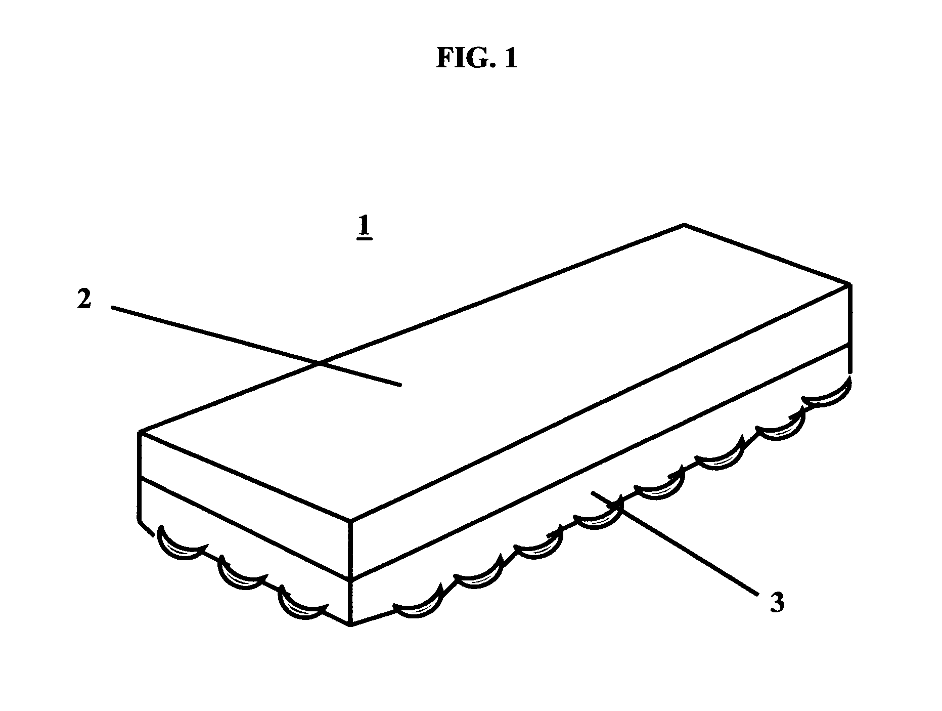
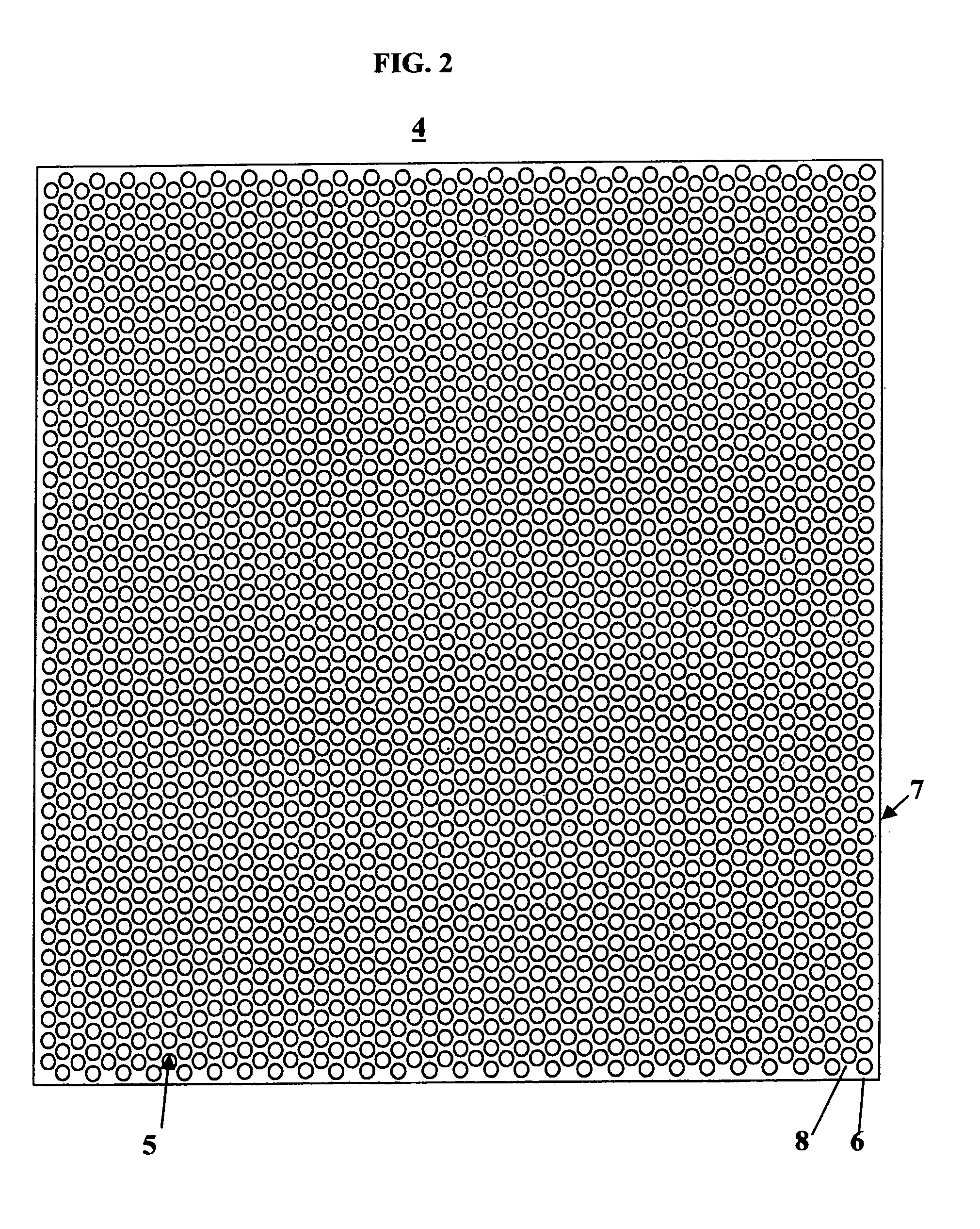
[0019]Referring to the drawings, FIG. 1 is a perspective view of one embodiment of a decorative surface covering 1 of the invention. The decorative layer 2 of the surface covering 1 c...


PUM

PropertyMeasurementUnit
areaaaaaaaaaaa
pressureaaaaaaaaaa
dimensionsaaaaaaaaaa

Abstract

This invention describes a decorative surface covering comprising at least one decorative layer and a backing layer comprising a patterned array of elastomeric, geometric projections, wherein each geometric projection comprises a concave exposed surface, an outside wall surface and an inside wall surface wherein the inside wall surface defines a hollow area within the projection. When the decorative surface covering is installed over an underlying surface, and pressure is applied to the decorative surface covering, a vacuum is created within the hollow area of the projections and the underlying surface. The vacuum increases the amount of frictional drag between the surface covering and the underlying surface, and thus allows the surface covering to remain in place without the need for an adhesive.

Description

CROSS-REFERENCE TO RELATED APPLICATIONS[0001]This application claims the benefit of U.S. Provisional Application No. 61 / 277,490, filed Sep. 26, 2009.FIELD OF THE INVENTION[0002]The present invention relates to decorative surface coverings, including flooring materials.BACKGROUND OF THE INVENTION[0003]Decorative surface coverings are typically installed upon a building surface. Resilient flooring products are typically adhered to a sub-floor surface using adhesives. These adhesives are either applied to the sub-floor, or in the cases of resilient tile products they can be applied to the back of the tile itself by the manufacturer. Flooring products must stay in place during use conditions which can include walking forces, dragging forces, rolling load forces, indentation forces, and sub-floor movement due to dimensional instability. Flooring products must stay flat, not curl, and seams, especially between tiles, must not move or open. Because of problems with adhesives, there have be...

Claims


Application Information

Patent Timeline
Patent Type & Authority Patents(United States)
IPC IPC(8): B32B3/00B32B1/00B32B3/12
CPCB32B3/10B32B25/14Y10T428/24628Y10T428/24612Y10T428/24479Y10T428/24661B32B3/30B32B5/18B32B7/12B32B25/04B32B25/042B32B25/045B32B25/08B32B25/12B32B27/30B32B2270/00B32B2307/734B32B2307/744B32B2471/00
Inventor REICHWEIN, DAVID P.POCOCK, KEITH A.
Owner GROWLIFE INC
Why Eureka
Try Eureka