Device for the non-destructive testing of parts in a turbomachine

a turbomachine and non-destructive testing technology, which is applied in the direction of magnetic property measurement, material magnetic variables, instruments, etc., can solve the problems of difficult access to turbomachine areas, limited access to this rod, and inability to always be possible, so as to facilitate the movement and positioning of the rod

Active Publication Date: 2012-10-30
SN DETUDE & DE CONSTR DE MOTEURS DAVIATION S N E C M A
View PDF7 Cites 22 Cited by
  • Summary
  • Abstract
  • Description
  • Claims
  • Application Information

AI Technical Summary

Benefits of technology

[0010]In this device, the blade that carries the inspection probe is configured so as to be introduced into very narrow spaces, in order to position the probe in places that are difficult to access in the turbomachine. The blade is relatively thin and may have a thickness less than or equal to approximately 1 mm. At rest it preferably has an elongate and slightly curved shape around its elongation axis. The blade according to the invention is advantageously elastically deformable in flexion, which makes it possible in particular to apply the probe with a certain pressure (corresponding to the elastic return force of the blade) on the surface of the part to be inspected, when this probe must be in abutment on the part during inspection. The support blade of the probe is also retractile or deployable on the finger between a retracted position in which it extends along and alongside the finger and a deployed or advanced position in which it extends in front of the finger. The blade is brought into the retracted position prior to the introduction of the rod in the turbomachine in order to protect the probe against any impacts with surrounding parts.
[0011]According to another feature of the invention, the finger is mounted so as to pivot by one of its ends on the distal end of the rod, about an axis substantially perpendicular to the longitudinal axis of the rod. This makes it possible to increase further the areas accessible to the device according to the invention. The pivoting of the finger can be controlled by a rigid or semi-rigid cable extending along the rod and connected at its distal end to the finger. In the present application, semi-rigid cable means a cable that is slightly deformable in flexion.
[0015]According to yet another feature of the invention, the blade is removably fixed to the finger or to the ring, which makes it possible in particular to replace the blade and therefore the probe when the latter is worn or when the probe or other particular type must be replaced by a probe of another type.
[0016]The device according to the invention can also comprise an optical observation channel extending along the rod and emerging at its distal end in the vicinity of the distal end of the rod. This makes it possible to visually inspect a part or the surroundings of a part during inspection thereof by means of the probe, or to facilitate the movement and positioning of the rod in the endoscope orifices or the passages of the turbomachine.

Problems solved by technology

In some cases, this testing may require the motor to be removed and partly dismantled in order to inspect parts that are difficult to access with the inspection means.
However, the area accessible to this rod is very limited and in general extends in line with the endoscopic orifice and at a short distance from this orifice.
In addition, when the probe carried by the rod must be used on a part to be inspected, this probe must be applied with a certain pressure and for a given period on a surface of this part, which is not always possible with the aforementioned device.
To access the lips of a labyrinth seal, the inspection probe must be passed through a very narrow space, which may have a width or axial dimension of approximately 1 mm, which is not possible with the aforementioned rod.
As a result some areas of a turbomachine remain difficult to access with the known non-destructive testing devices, since these are not designed to pass through orifices or passages of small size and through several orifices and / or non-aligned consecutive passages.

Method used


Image

  • Device for the non-destructive testing of parts in a turbomachine
  • Device for the non-destructive testing of parts in a turbomachine
  • Device for the non-destructive testing of parts in a turbomachine

Examples


Embodiment Construction

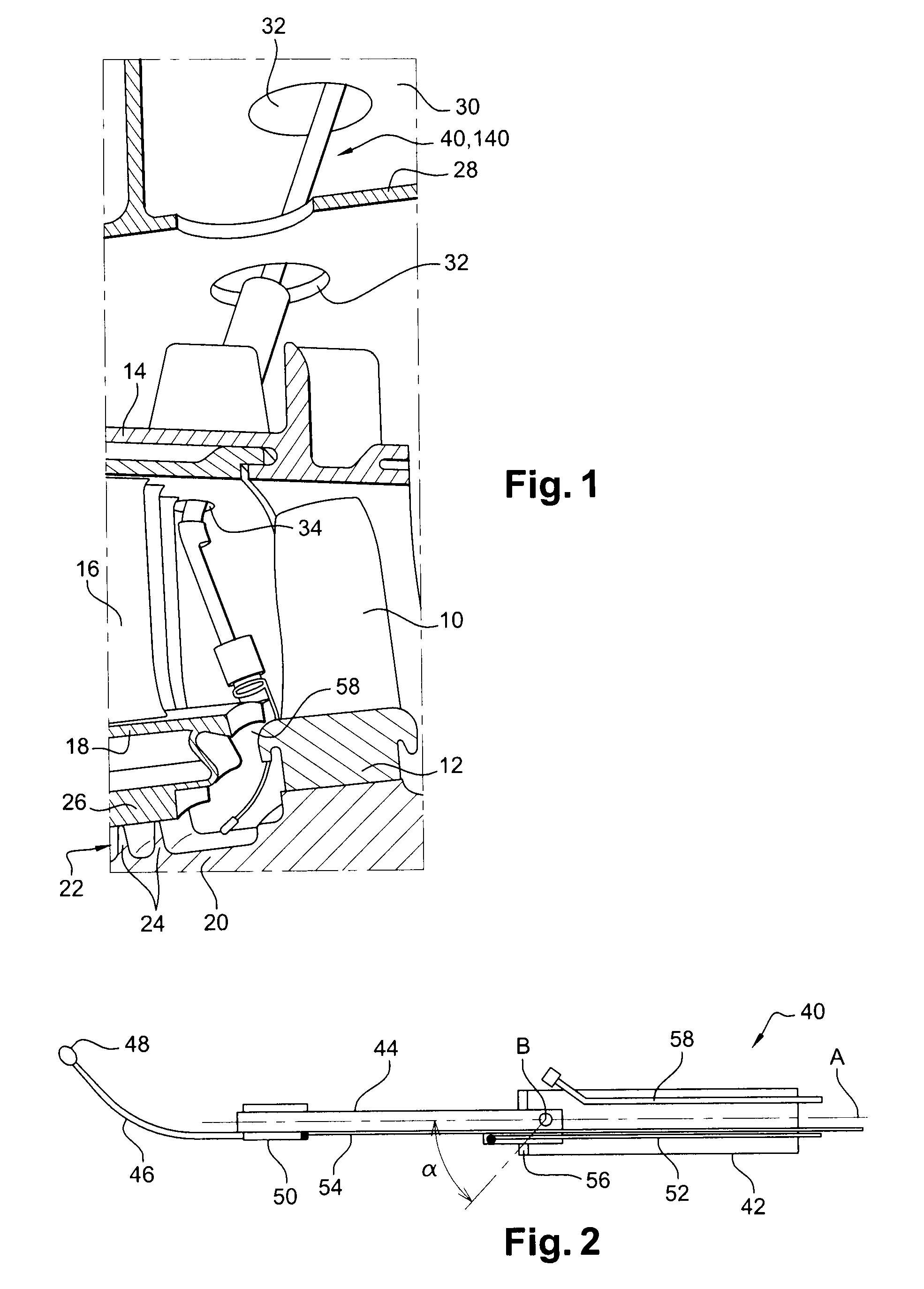
[0024]Reference is made first of all to FIG. 1, which shows schematically a part of a turbomachine, in particular a turbine or compressor stage of this turbomachine.

[0025]This turbine or compressor stage comprises an annular row of rotor blades 10 carried by a disc 12 and rotating inside a substantially cylindrical wall 14, and an annular row of stator blades 16 disposed upstream of the rotor blades 10 and carried at their radially external ends by the wall 14. The stator blades 16 are connected at their radially internal ends to an annular platform 18, this platform 18 and the external periphery of the disc 12 delimiting with the wall 14 the gas flow stream in the turbomachine.

[0026]The platform18 surrounds a substantially cylindrical rotor wall 20 connecting the rotor disc 12 to another rotor disc (not visible) situated upstream of the stator blades 16.

[0027]A seal of the labyrinth type is mounted between the rotor wall 20 and the platform 18, and comprises annular lips 24 extendi...


PUM

PropertyMeasurementUnit
thicknessaaaaaaaaaa
widthaaaaaaaaaa
angleaaaaaaaaaa

Abstract

A device for the non-destructive testing of parts of a turbomachine motor, including a longitudinal rod carrying at its distal end a longitudinal finger carrying a retractile or deployable flexible blade supporting an inspection probe, this blade being guided in axial translation on the finger between a retracted position in which it extends along the finger and an advanced or deployed position in which it extends in front of the finger.

Description

[0001]The present invention concerns a device for the non-destructive testing of parts of a motor, in particular of a turbomachine.BACKGROUND OF THE INVENTION[0002]Non-destructive testing (NDT) of parts of a turbomachine motor makes it possible to check the state of these parts without damaging them. In some cases, this testing may require the motor to be removed and partly dismantled in order to inspect parts that are difficult to access with the inspection means.[0003]A known inspection device comprises a rigid rod carrying a test probe or sensor at its distal end. Where the turbomachine is equipped with endoscopic orifices, this rod is introduced into the turbomachine through one of these orifices for the in situ inspection of parts of the turbomachine, which avoids removing the motor.[0004]However, the area accessible to this rod is very limited and in general extends in line with the endoscopic orifice and at a short distance from this orifice. In addition, when the probe carri...

Claims


Application Information

Patent Timeline
Patent Type & Authority Patents(United States)
IPC IPC(8): G01N27/72G01N27/82
CPCG01N27/9033G01N27/9006
Inventor BOUSQUET, SADIAGAISNON, PATRICKMOZER, SYLVIESAMAK, NICOLAS
Owner SN DETUDE & DE CONSTR DE MOTEURS DAVIATION S N E C M A
Why Eureka
Try Eureka