Movement amplifying actuation device

Active Publication Date: 2021-04-22
CENT NAT DE LA RECHERCHE SCI +2
View PDF0 Cites 0 Cited by
  • Summary
  • Abstract
  • Description
  • Claims
  • Application Information

AI Technical Summary

Benefits of technology

[0099]a second actuation arm configured to effect a movement in translation relative to the fixed base and adapted to apply to a second transmission arm connected to a second fixing point of the fixed base by a flexible connection articulated about the second axis a movement in rotation relative to said fixe

Problems solved by technology

In other words, known micro-actuators do not address the

Method used


Image

  • Movement amplifying actuation device
  • Movement amplifying actuation device
  • Movement amplifying actuation device

Examples


Embodiment Construction

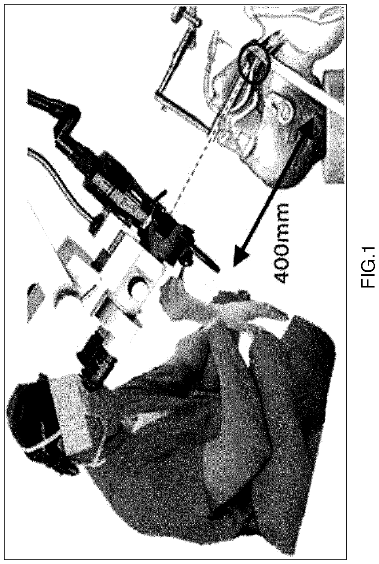
[0128]FIG. 1 shows a prior art laser microsurgery method that was described in the introduction to the present application and will not be described again here.

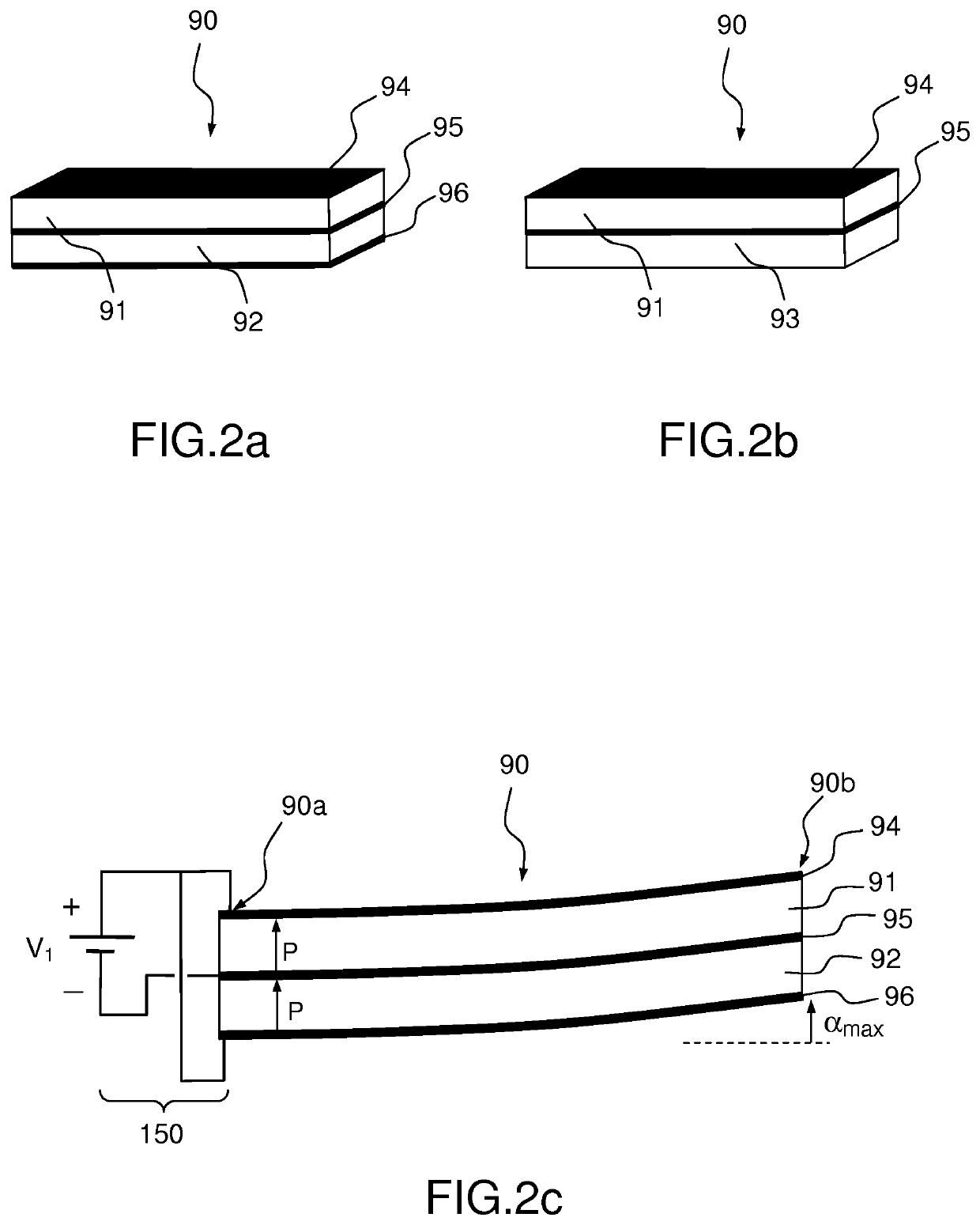
[0129]FIGS. 2a, 2b and 2c, which show examples of prior art bimorph or unimorph piezoelectric beams, were described in the introduction to the present application and will not be described again here.

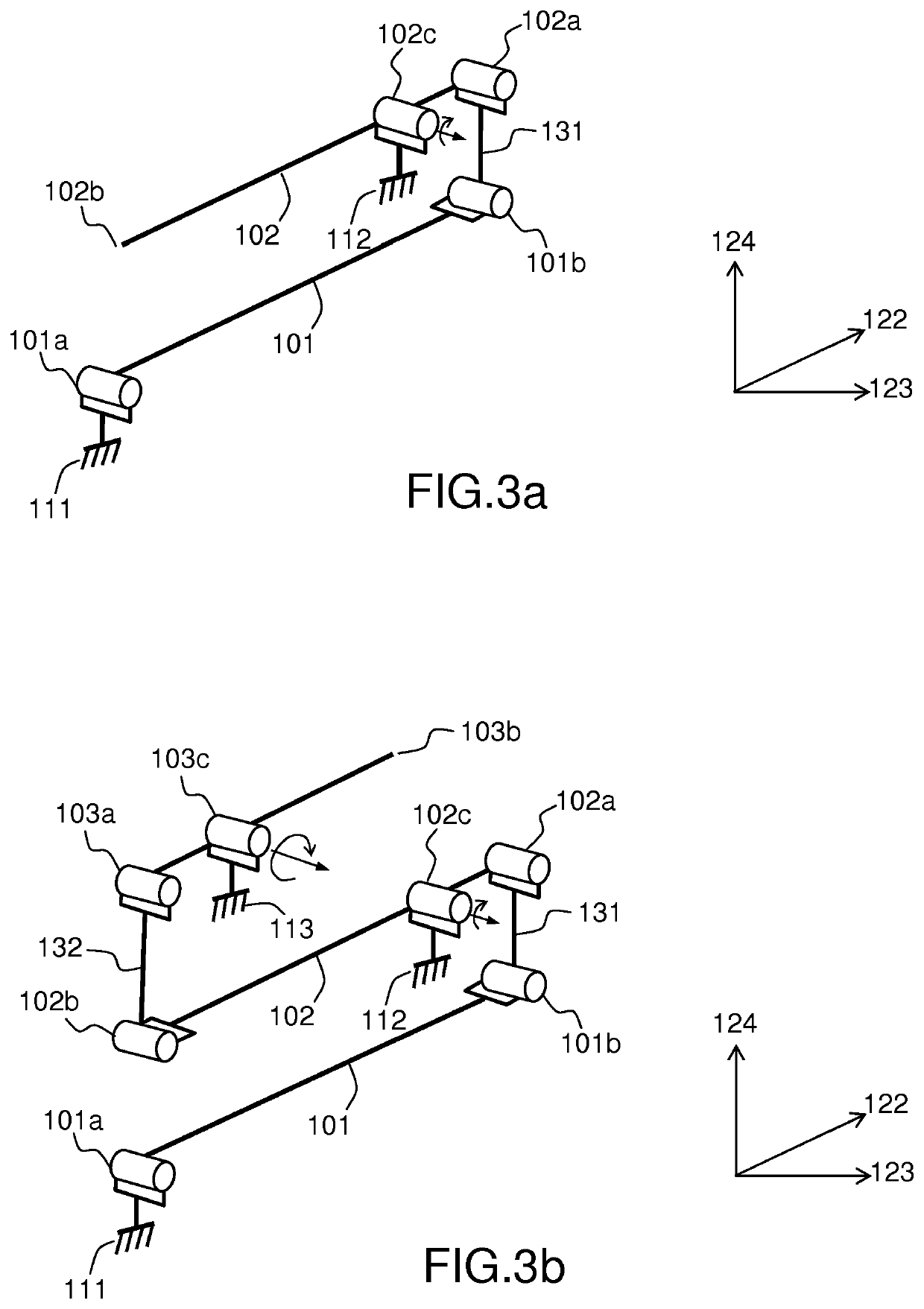
[0130]FIGS. 3a and 3b provide 3D theoretical diagrams of two actuation devices according to the invention, the first with two beams and the second with three beams. They will be described at the same time as FIGS. 4a and 4b which are diagrammatic 2D views of the same two examples and further indicate the movements in flexing. These figures are kinematic views.

[0131]The actuation device represented in FIGS. 3a and 4a comprises a first piezoelectric beam 101 adapted to flex about a principal axis 124 when a voltage is applied to it attached at a first end 101a to a fixed point 111 and a second piezoelectric beam 102 also adapted to...


PUM


Abstract

Movement amplifying actuation device (100) comprising at least two piezoelectric beams (101, 102, 103), one beam (101) being attached at a fixed point (111), and at least one hinge (131, 132) connecting a first beam (101, 102) and a second beam (102, 103) between them. Each hinge comprises: a first flexible portion connected to the first beam, a second flexible portion connected to the second beam, a first rigid portion connecting the first and second flexible portions, a second rigid portion capable of being positioned against a fixed point (112, 113), and third flexible portion connecting the second beam to the second rigid portion at a pivot point of said second beam such that the assembly formed by the second rigid portion and the second beam forms a lever around said pivot point. Said flexible and rigid portions form a single piece.

Description

TECHNICAL FIELD OF THE INVENTION[0001]The invention relates to amplified actuation devices, to be more precise miniaturized devices, occupying a volume of the order of ten cubic millimeters.[0002]The invention may find numerous applications, in particular for actuating a platform. That platform may receive a mirror to reflect a laser beam. The laser beam can therefore be used for laser marking and / or etching, for 3D scanning, in the field of (micro)robotics (for example laser vision), in the field of telecommunications (for example for a variable optical attenuator or an optical switch), or for medical applications (relatively non-invasive endoscopic surgery, optical exploration with or without biopsy, etc.).[0003]The invention was specifically developed for laser microsurgery of the vocal cords, or phono-surgery, with the objective of guiding a laser beam precisely toward the vocal cords. The so termed phono-surgery is defined as follows: “all surgical procedures that maintain, res...

Claims


Application Information

Patent Timeline
IPC IPC(8): B25J9/00A61B34/00B25J7/00B25J9/12H02N2/04H02N2/10
CPCB25J9/0015A61B34/72B25J7/00H02N2/108B25J9/12H02N2/046B25J9/003B25J18/005H10N30/2044H02N2/00
Inventor LESCANO, SERGIOANDREFF, NICOLASRAKOTONDRABE, MICKYRABENOROSOA, KANTYTAMADAZTE, BRAHIMBOUDERLIQUE, CLÉMENT
Owner CENT NAT DE LA RECHERCHE SCI
Why Eureka
Try Eureka