Roof ventilation system

a ventilation system and roof vent technology, applied in ventilation systems, lighting and heating apparatus, heating types, etc., can solve the problems of not providing a desirable sealable surface between the ridge vent system and the underlying roof, not providing a method for draining moisture, and not providing a desirable sealable surfa

Active Publication Date: 2012-11-06
BAHN RICHARD STUART
View PDF24 Cites 15 Cited by
  • Summary
  • Abstract
  • Description
  • Claims
  • Application Information

AI Technical Summary

Benefits of technology

[0004]The present invention provides an improved air permeable ventilation sealant system for a ridge vent found in building structures wherein the sealant strip can be positively sealed to the underlying roof and the upper ridge cap while allowing for removal of moisture that has accumulated on the interior side of the ridge vent system with the use of a lip, angled surfaces and a moisture channel.

Problems solved by technology

One problem is that insects, rain, moisture, or other undesirable elements can also pass through the openings into the structure.
Since the reticulated material is a very open material that does not present a continuous flat, smooth surface to the underlying roof, it does not provide a desirable sealable surface between the ridge vent system and the underlying roof.
U.S. Pat. No. 6,773,342 recognized the problem of moisture on the interior of a vent system with an upper water barrier and a lower water dam to attempt to prevent water from entering but again does not provide a method for draining the moisture once present.
U.S. Pat. No. 5,826,383 and U.S. Pat. No. 6,079,166 attempt to drain the moisture on the interior of a vent system once the moisture is present by including weep holes, however this method has not proved to be as effective as desired.

Method used


Image

  • Roof ventilation system
  • Roof ventilation system
  • Roof ventilation system

Examples


Embodiment Construction

[0019]The present invention relates to the general field of roof ventilation systems. More specifically an improved air permeable roof closure ventilation. The following description is presented to enable one of ordinary skill in the art to make and use the invention and to incorporate it in the context of particular applications. Various modifications, as well as a variety of uses in different applications will be readily apparent to those skilled in the art, and the general principles defined herein may be applied to a wide range of embodiments. Thus, the present invention is not intended to be limited to the embodiments presented, but is to be accorded the widest scope consistent with the principles and novel features disclosed herein.

[0020]Overview:

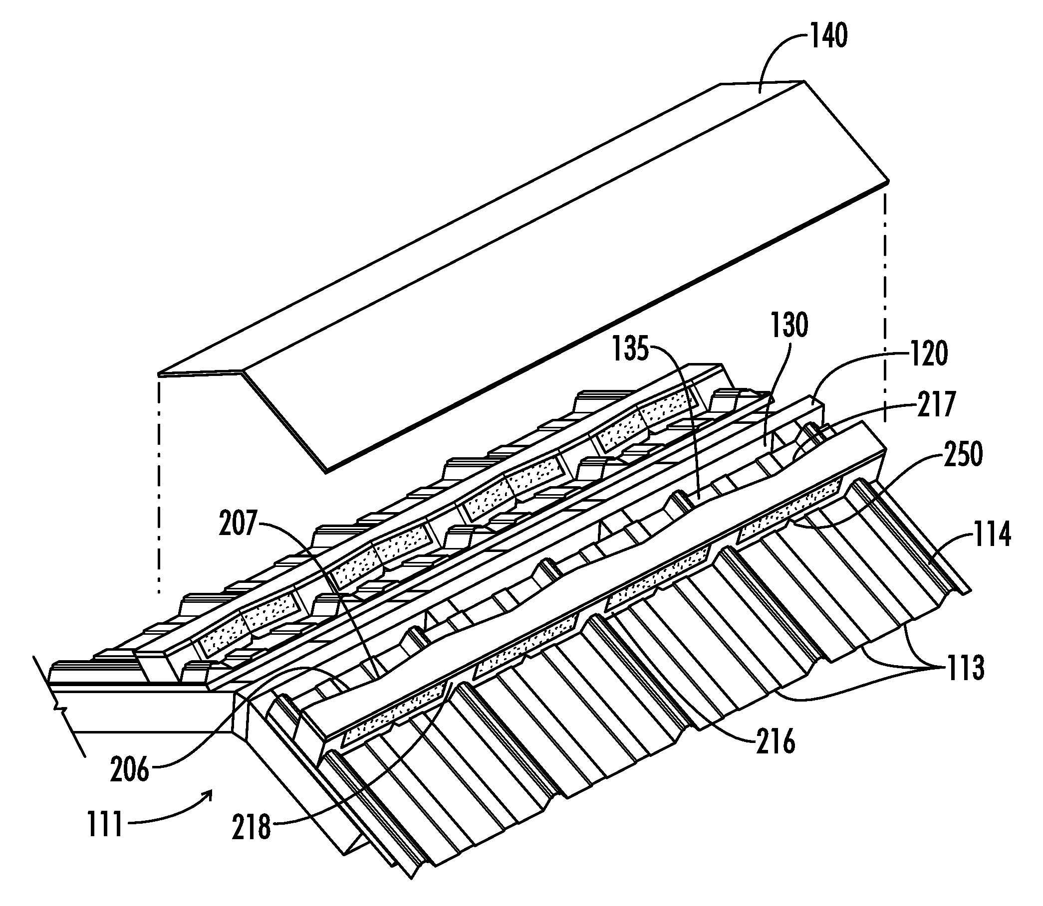
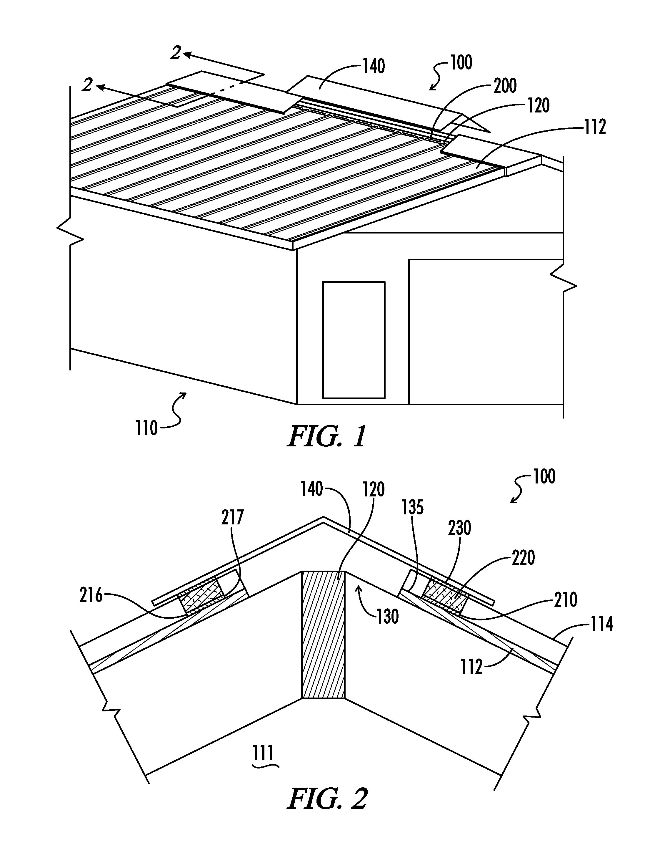
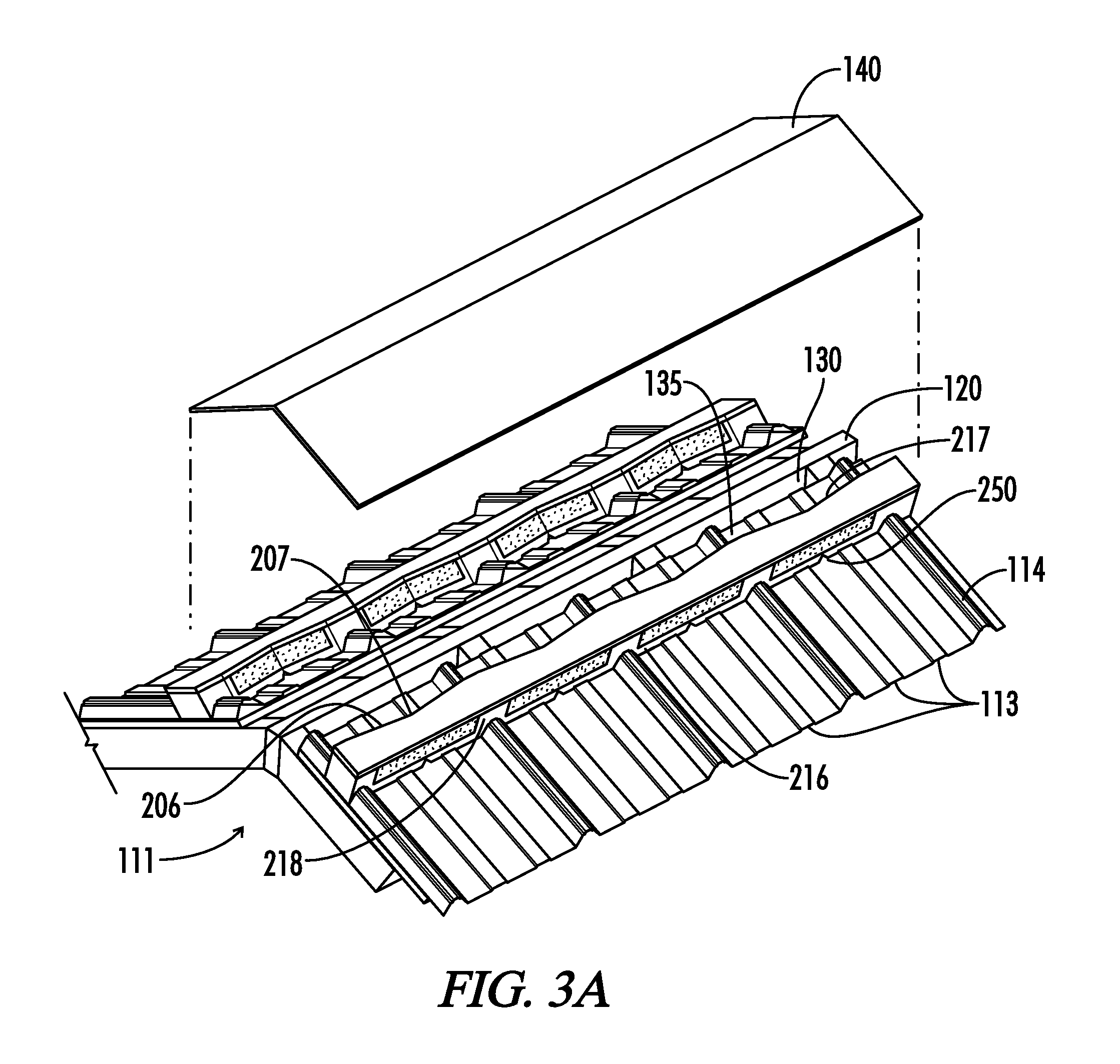
[0021]As illustrated in FIGS. 1 through 10, a roof closure ventilation system 100 comprises a structure 110 that includes a sloped roof 112 having multiple roofing sections joined at one or more sides with elongated ribs or overlappin...


PUM


Abstract

A roof vented closure strip 200 comprises profile piece 210, filter material 220, and top layer 230, the strip manufactured with at least two different materials combining to fill the space between a ridge cap 140 and a sloped roof 112. The profile piece includes a lower surface 213, side surfaces 215, a front exterior surface 216, a rear interior surface 217. The strip is disposed on the sloped roof such that a lip is formed between strip rear interior surface, and the ridge slot. Filter material fills between the profile piece, the top layer, the front exterior surface, and the rear interior surface wherein the rear interior surface slopes at an angle 206 toward front exterior surface, and one or more moisture channel 250 extends laterally across the width of the strip, such that moisture flows from the lip down and drains through the moisture channel exiting the structure.

Description

FIELD OF INVENTION[0001]The present invention relates to the general field of roof ventilation systems. It is specifically related to air permeable roof ridge ventilation.BACKGROUND OF INVENTION[0002]It is common to ventilate attics and roofs of building structures to remove stagnant or hot air with ventilating systems. A common ventilating system includes an open slot running along the length of the roof ridge causing ventilation of the attic by convection airflow and the wind blowing across the roof creating a negative pressure and moving the interior air to the exterior. The vents are provided to permit ingress and egress of gas or air. Ridge vents are typically combined with gable or soffit vents through which air can flow into the space below the roof to encourage a continuous flow of air from the ambient environment, through the space beneath the roof and back to the ambient environment through the ridge vent.[0003]For centuries inventors have tried to solve problems associate...

Claims


Application Information

Patent Timeline
Patent Type & Authority Patents(United States)
IPC IPC(8): E04B7/00F24F7/02
CPCE04D13/174
Inventor BAHN, RICHARD STUART
Owner BAHN RICHARD STUART
Why Eureka
Try Eureka