

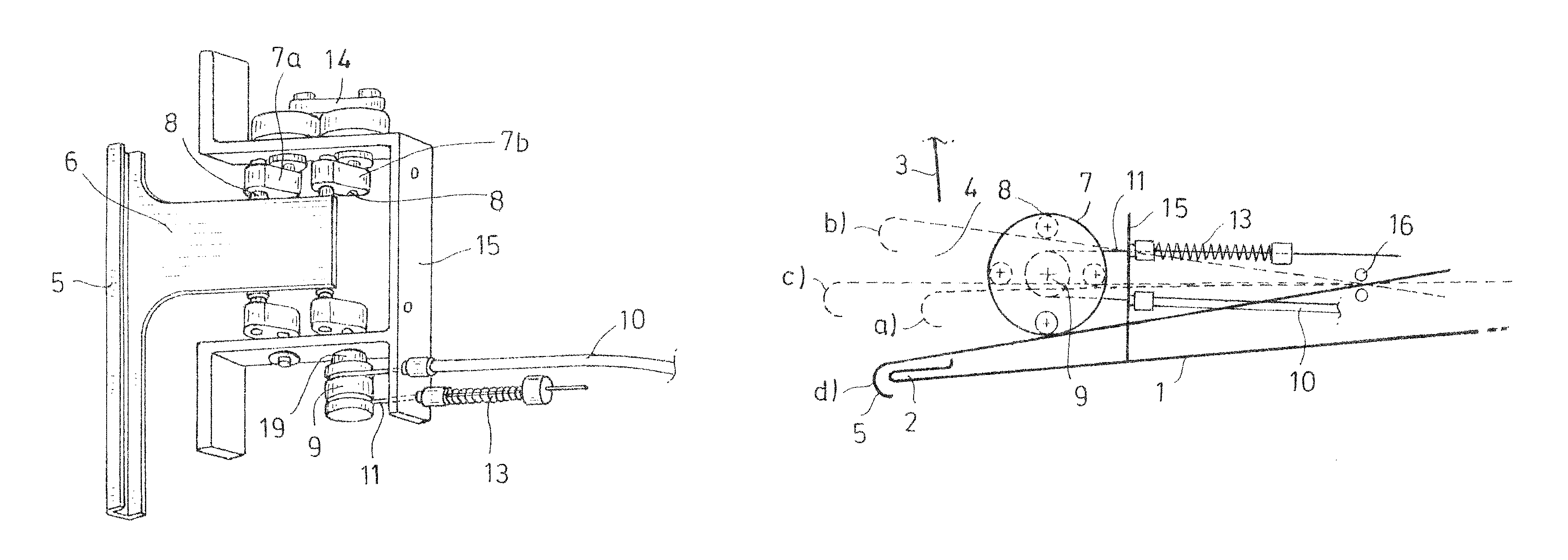
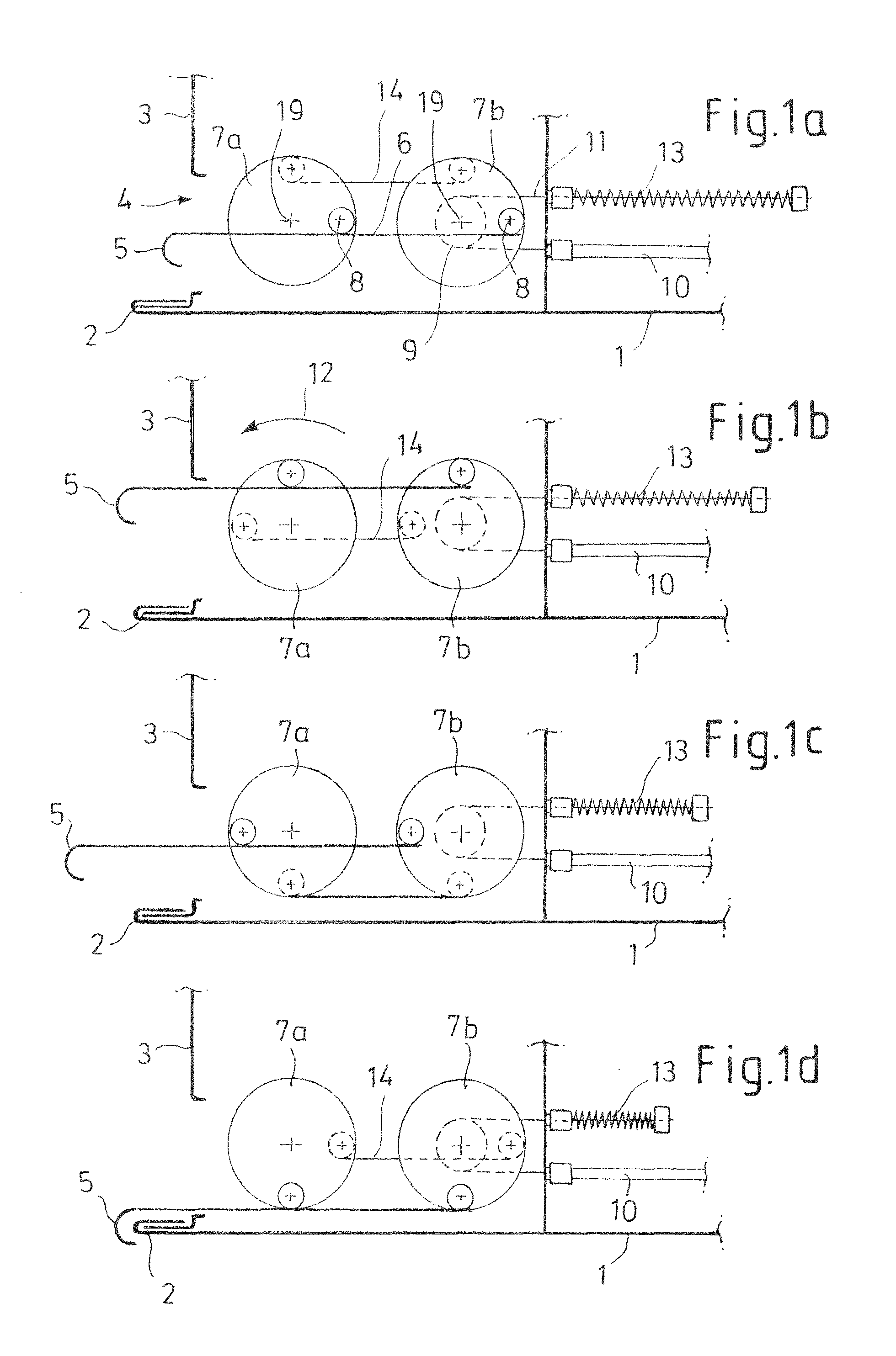
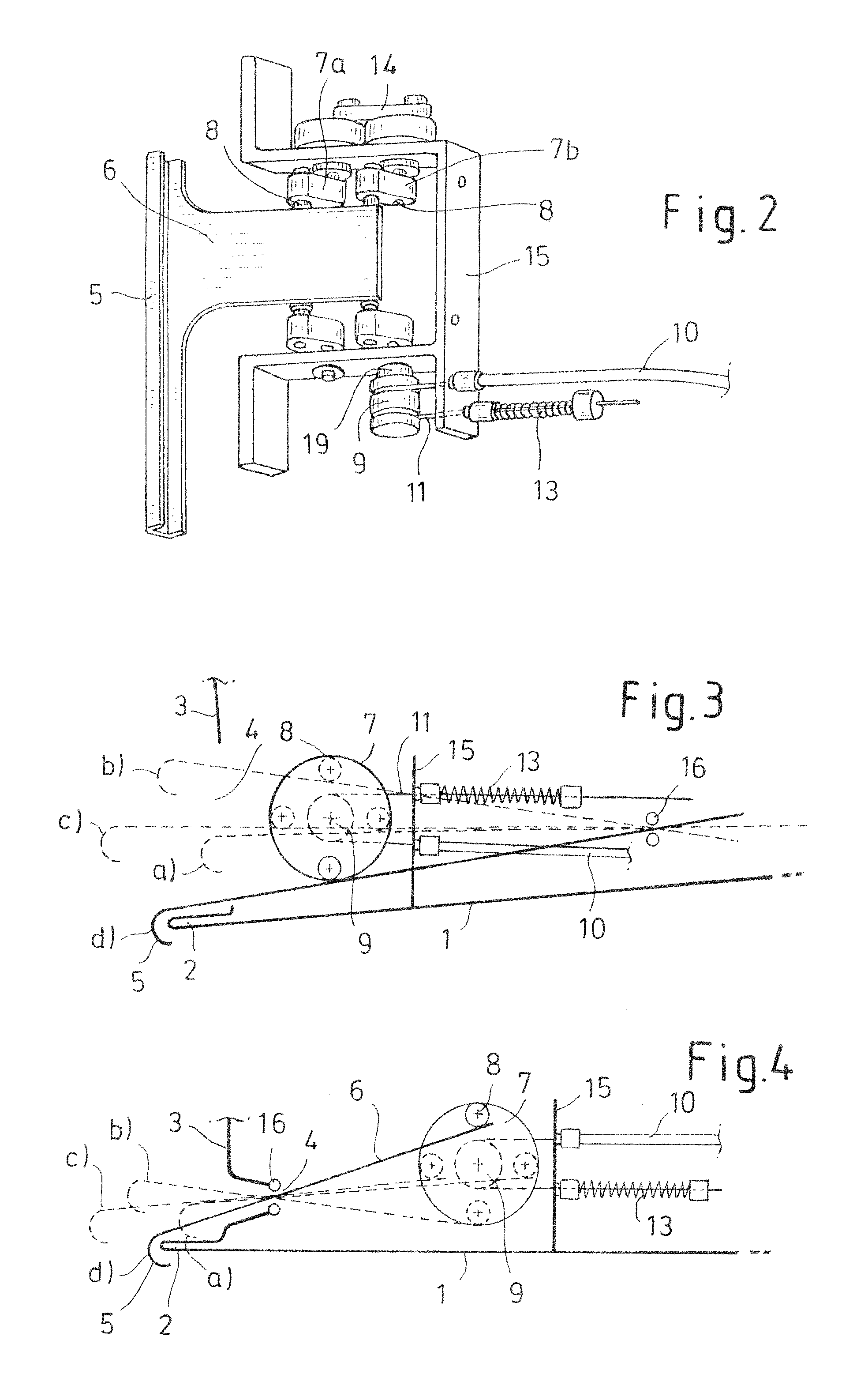
Door edge protection device
a protection device and door edge technology, applied in the direction of bumpers, wing knobs, roofs, etc., can solve the problems of occupying a large space, affecting the safety of passengers, and unable to move the edge protection device,
- Summary
- Abstract
- Description
- Claims
- Application Information
AI Technical Summary
Benefits of technology
Problems solved by technology
Method used
Image

Examples
Embodiment Construction
[0013]For purposes of description herein, the terms “upper,”“lower,”“right,”“left,”“rear,”“front,”“vertical,”“horizontal,” and derivatives thereof shall relate to the invention as orientated in FIG. 1. However, it is to be understood that the invention may assume various alternative orientations, except where expressly specified to the contrary. It is also to be understood that the specific devices and processes illustrated in the attached drawings, and described in the following specification are simply exemplary embodiments of the inventive concepts defined in the appended claims. Hence, specific dimensions and other physical characteristics relating to the embodiments disclosed herein are not to be considered as limiting, unless the claims expressly state otherwise.
[0014]According to an aspect of the present invention, since a door edge protection member is driven via an eccentric lever mounted rotatably in the door, the door edge protection member can move along a predetermined ...
PUM
 Abstract
Description
Claims
Application Information