
Method and apparatus for tracking points in an ultrasound image

a technology of ultrasound image and point tracking, applied in the field of ultrasound imaging, can solve the problems of not having a method to ensure proper accounting of each structure, difficult to ensure, and difficult to determine whether a structure that is currently visualized is newly identified or has already been identified and counted

Active Publication Date: 2012-11-06
GENERAL ELECTRIC CO
View PDF10 Cites 78 Cited by
  • Summary
  • Abstract
  • Description
  • Claims
  • Application Information

AI Technical Summary

Benefits of technology

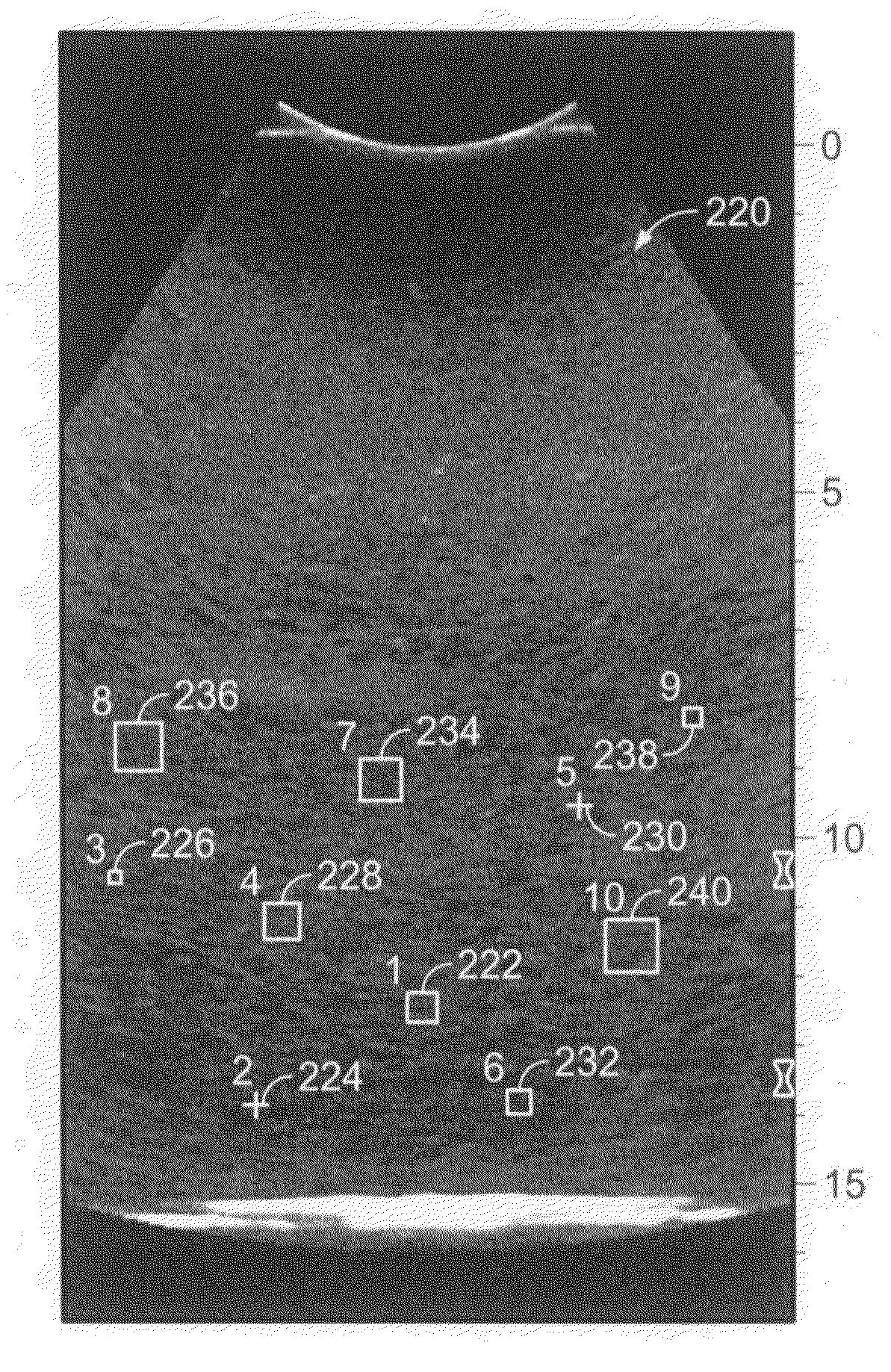
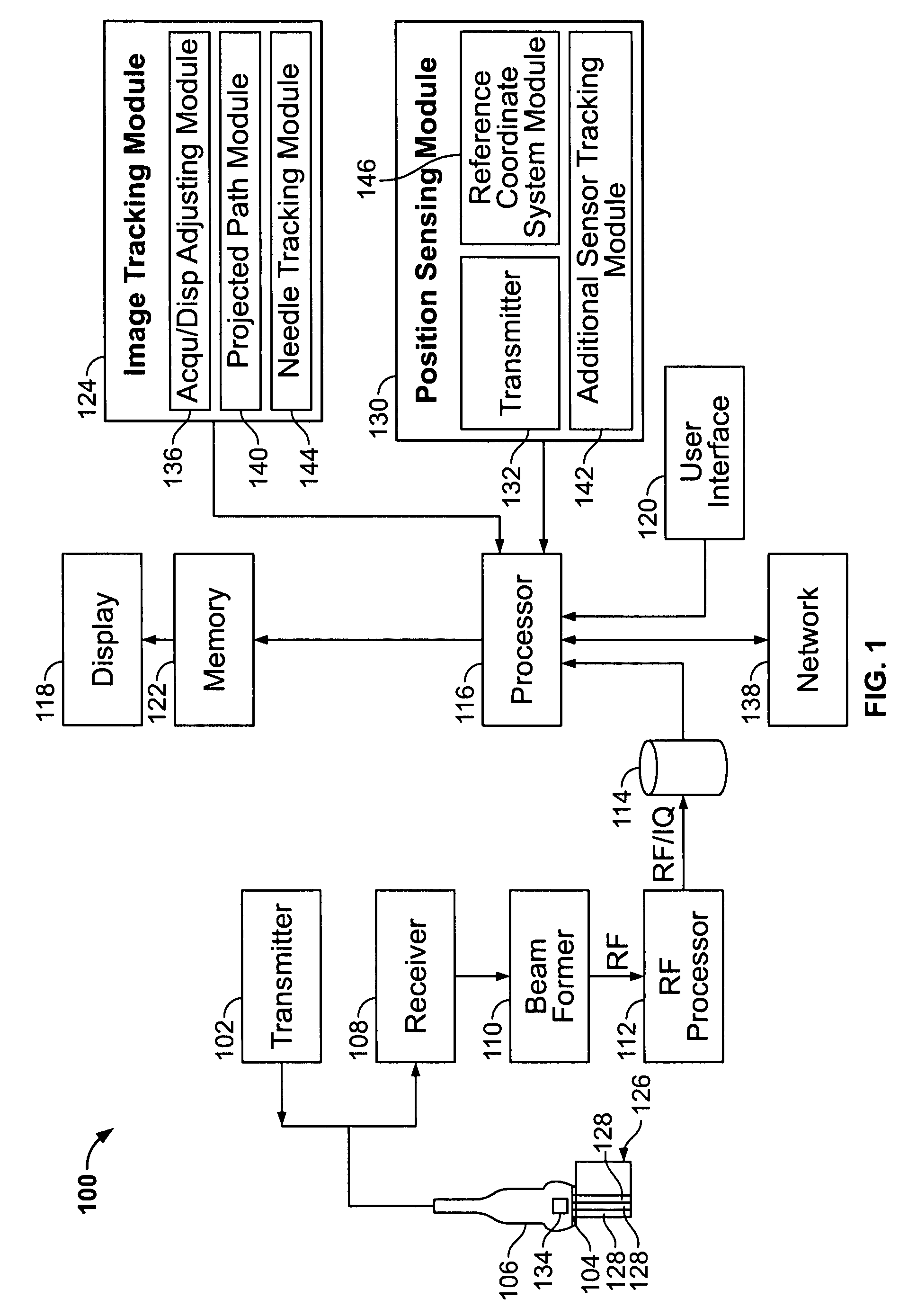
"The patent describes an ultrasound system that uses position sensing technology to track the movement of structures within a diagnostic imaging dataset. The system includes a position sensing module, an imaging tracking module, a display, and a user interface. The position sensing module detects spatial information associated with a volume of data, and the display shows first and second images based on the volume of data. The first and second images have different portions that are at least partially different. The user interface selects a first image tracking point on the first image, which is indicated on the first image with a first indicator. The image tracking module tracks the first image tracking point within the volume of data, and the display shows the spatial relationship of the first image tracking point to the second image. This technology allows for more precise and accurate tracking of structures within the imaging dataset, which can improve the accuracy and reliability of ultrasound imaging."

Problems solved by technology

However, there is currently no method to ensure proper accounting for each structure.
Unfortunately, it can be difficult to ensure that each occurrence or structure is counted exactly one time as the user navigates through an organ or other volume in the body.
As the imaging angle of the probe or the location of the probe on the patient changes, it is difficult to determine whether a structure that is currently visualized is newly identified, or has already been identified and counted.
This may be increasingly complicated if there are many structures to count and may lead to a lower level of diagnostic confidence.
This can be time-consuming and laborious, especially when there are many structures.
If the structure is small, it may be difficult to detect, requiring additional time to locate and identify the structure from another view, or to determine that the structure may not be adequately viewed from that angle.
It may be difficult to locate the structure of interest again when the user returns to the same original viewing angle.

Method used


Image

  • Method and apparatus for tracking points in an ultrasound image
  • Method and apparatus for tracking points in an ultrasound image
  • Method and apparatus for tracking points in an ultrasound image

Examples


Embodiment Construction

[0019]The foregoing summary, as well as the following detailed description of certain embodiments of the present invention, will be better understood when read in conjunction with the appended drawings. To the extent that the figures illustrate diagrams of the functional blocks of various embodiments, the functional blocks are not necessarily indicative of the division between hardware circuitry. Thus, for example, one or more of the functional blocks (e.g., processors or memories) may be implemented in a single piece of hardware (e.g., a general purpose signal processor or random access memory, hard disk, or the like). Similarly, the programs may be stand alone programs, may be incorporated as subroutines in an operating system, may be functions in an installed software package, and the like. It should be understood that the various embodiments are not limited to the arrangements and instrumentality shown in the drawings.

[0020]FIG. 1 illustrates a block diagram of an ultrasound sys...


PUM


Abstract

An ultrasound system comprises a position sensing module, an imaging tracking module, a display and a user interface. The position sensing module detects spatial information associated with a volume of data. The display displays first and second images based on the volume of data. The first and second images comprise first and second portions of the volume of data, and the first and second portions are at least partially different with respect to each other. The user interface selects a first image tracking point on the first image. The first image tracking point is indicated on the first image with a first indicator. The image tracking module tracks the first image tracking point within the volume of data. The image tracking module indicates on the display a spatial relationship of the first image tracking point to the second image.

Description

BACKGROUND OF THE INVENTION[0001]This invention relates generally to ultrasound imaging, and more particularly, to tracking points of interest within an ultrasound image.[0002]Ultrasound is used for non-invasive diagnostic imaging and with invasive surgical techniques, such as biopsies and ablations. Typically, a user moves an ultrasound probe about a patient to acquire two-dimensional (2D) views, 3D and / or 4D volume representations of anatomy and items or structures of interest within the patient's body. However, there is currently no method to ensure proper accounting for each structure.[0003]While scanning, there is often a need to count the number of structures, points, or items in the body, such as the number of nodules in the thyroid or the number of metastases in the liver. Unfortunately, it can be difficult to ensure that each occurrence or structure is counted exactly one time as the user navigates through an organ or other volume in the body. This is especially true when a...

Claims


Application Information

Patent Timeline
Patent Type & Authority Patents(United States)
IPC IPC(8): A61B8/00
CPCA61B8/00A61B8/4245A61B8/483G03B42/06G01S7/52073G01S15/8993G01S7/52036A61B8/145G01S7/52065A61B8/4254
Inventor WASHBURN, MICHAEL JOSEPHMARQUART, MARKUS WILHELMSHELJASKOW, TODOR
Owner GENERAL ELECTRIC CO
Learn More