
Rheolytic thrombectomy catheter with self-inflating distal balloon

a thrombus and distal balloon technology, applied in the field of thrombus removal catheters, can solve the problems of affecting the effectiveness of thrombosis, affecting so as to optimize the effect of thrombosis, enhance the efficacy of thrombosis, and stop and/or impede blood flow in the vessel

Active Publication Date: 2012-11-06
BOSTON SCI MEDICAL DEVICE LTD
View PDF238 Cites 15 Cited by
  • Summary
  • Abstract
  • Description
  • Claims
  • Application Information

AI Technical Summary

Benefits of technology

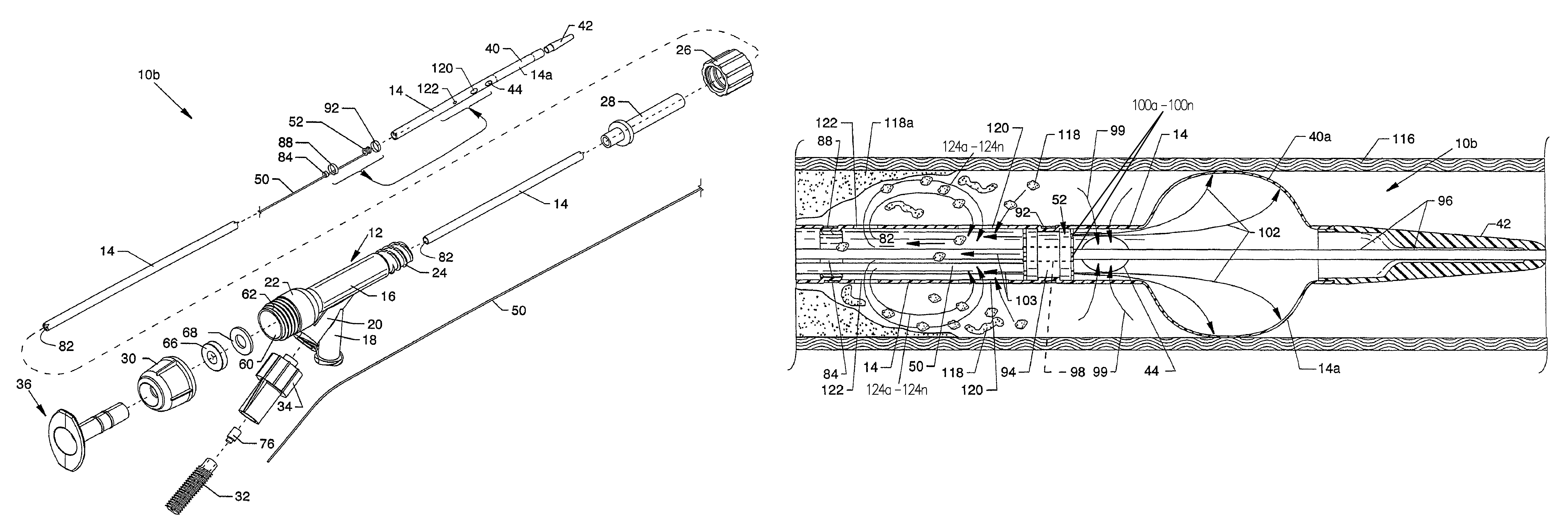
[0010]The general purpose of the devices of the present disclosure are to provide a rheolytic thrombectomy catheter with a self-inflating distal balloon, also referred to as a rheolytic thrombectomy catheter and system sold under the trademark AngioJet®, to elegantly stop and / or impede blood flow in a vessel while simultaneously increasing the efficacy of thrombus removal. Flow cessation optimizes the effectiveness of thrombectomies, embolization containment, and procedures involving drug infusion, as well as minimizing hemolysis. Furthermore, the distal balloon is capable of pulling tough plug material within a conduit, i.e., an embolectomy. Other issues addressed by use of the devices of the present disclosure relate to catheter centering which enables more aggressively sized inflow windows for enhanced performance. Use of devices of the present disclosure also relate to modified embolectomies.
[0012]The device is a rheolytic thrombectomy catheter and can be used for removal of thrombus in coronary arteries, peripheral arteries or veins, neurological arteries or veins, or arterial venous conduits. By sizing the balloon for the intended vessel, the expanded balloon will be more efficacious in removing more organized clots and could be used just to increase the amount of debris / thrombus removed from a particular vessel length. Use of the device can minimize any distal or proximal embolization and can be used to deliver drugs more effectively in a stagnant field. The distally located balloon can also be used for centering or positioning of the device in a vessel. Finally, the devices of the present disclosure can be used to minimize hemolysis during operation of the AngioJet® catheter.
[0013]The present disclosure describes the addition of a self-inflating distal balloon to any of the AngioJet® catheter models. The self-inflating balloon is distally located with respect to a high velocity fluid jet stream emanator. Although balloons attached to catheters proximally or distally have been suggested in the past, this concept goes one step further by creating a self-inflating balloon out of the distal exhaust tube (Pebax® material or polyurethane, etc.) while using the exhaust pressure of the high velocity fluid jet streams to fill and sustain the self-inflating balloon for purposes of distal protection or occlusion. This arrangement minimizes profile, minimizes the number of components and design complexity, minimizes manufacturing costs, and is very easy to use since the self-inflating balloon is deployed automatically when the rheolytic thrombectomy catheter is activated.
[0014]Since AngioJet® catheters remove debris more effectively in a stagnant flow, this device has several applications. Thrombus will in some cases have tough end caps. Thus, if the device is deployed distally and then retracted during activation, the cap material could be withdrawn (potentially into a large introducer sheath). With this in mind, the device should also minimize any distal or proximal embolization. It could also be used to deliver drugs more effectively in a stagnant field. The self-inflating balloon could also be used for centering or positioning the catheter in a vessel to minimize vessel damage caused by unequal cross stream jet positioning. The occlusion of the blood field during activation should also minimize hemolysis. Finally, the self-inflating balloon could also be used to break up clots as it is moved through a blocked vessel, thereby performing a modified embolectomy.
[0021]Another significant aspect and feature of the devices of the present disclosure is a self-inflating distal balloon which is used for the purpose of the cessation of fluid flow in a blood vessel or other conduit in order to maximize the effect of a thrombectomy catheter in terms of debris or tissue removal.
[0022]Another significant aspect and feature of the devices of the present disclosure is a self-inflating distal balloon which is used for the purpose of the cessation of fluid flow in a blood vessel or other conduit in order to maximize the effect of a thrombectomy catheter in terms of debris or tissue removal from a distal protection filter wire or balloon.

Problems solved by technology

In general, placing an occlusion device proximally at the guide catheter or the use of a distal protection device will result in the need to upsize the interventional sheath or will result in a substantial increase in the cost of the procedure, or both.
In previously designed cross flow thrombectomy catheters, vessel damage is primarily inflicted by the inflow orifices.
The vessel wall can be sucked in by the negative pressures at the inflow orifices to the point that the internal high velocity jet streams can damage the vessel wall.
In fact, merely moving the catheter while the inflow orifices have been sucked onto the vessel wall is a likely mechanism for vessel damage from cross stream catheters.
Vessel damage increases with the size of the inflow orifices and with the proximity of the high velocity fluid jet stream origin to the inlet orifice.

Method used


Image

  • Rheolytic thrombectomy catheter with self-inflating distal balloon
  • Rheolytic thrombectomy catheter with self-inflating distal balloon
  • Rheolytic thrombectomy catheter with self-inflating distal balloon

Examples


Embodiment Construction

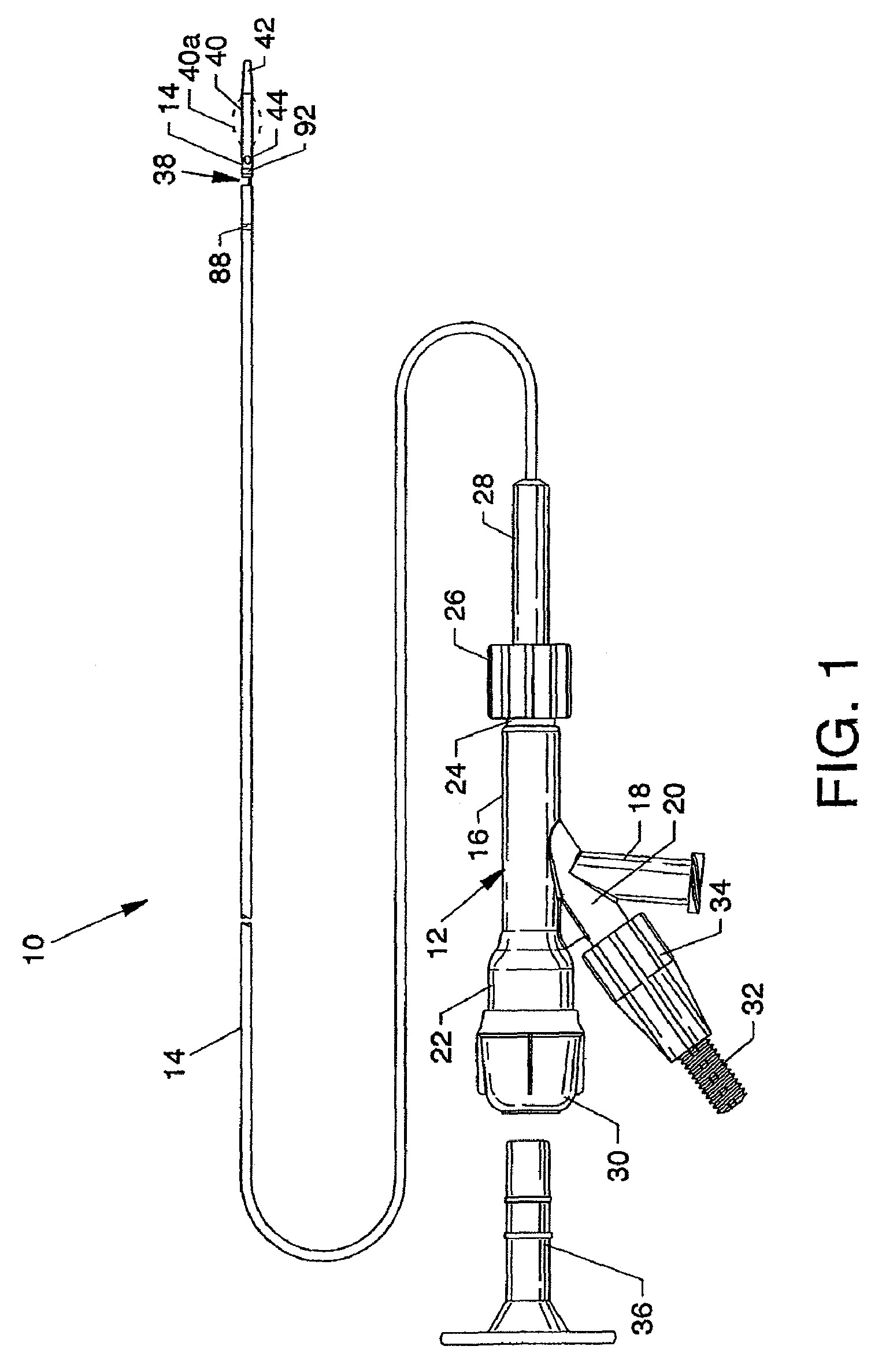
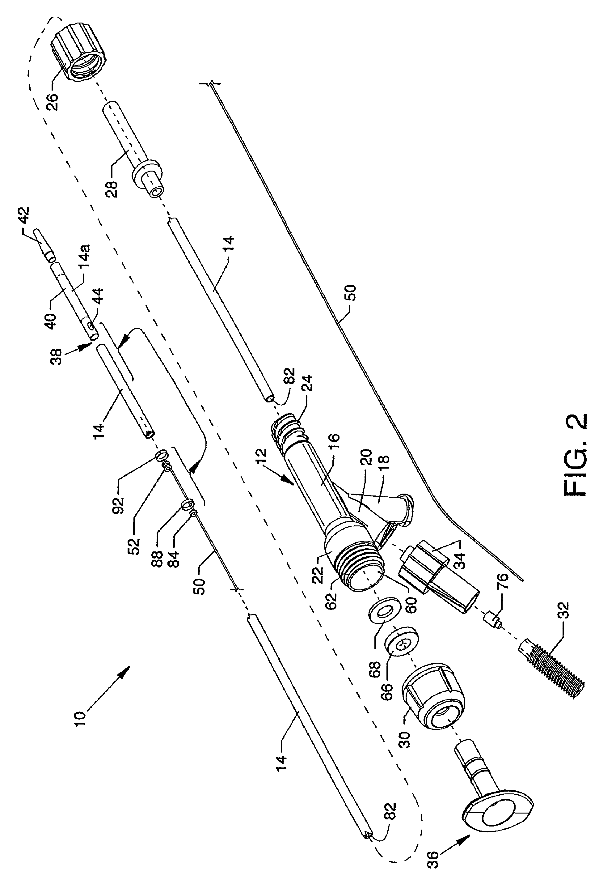
[0051]FIG. 1 is a plan view of the visible components of rheolytic thrombectomy catheter 10. The device includes a one-piece manifold 12 having multiple structures extending therefrom or attached thereto, and also includes a flexible catheter tube 14, preferably constructed of one or more sections of Pebax® material, and other components associated therewith as described herein. The visible portion of the one-piece manifold 12 includes a central tubular body 16 (e.g., central elongated tubular body), a threaded exhaust branch 18 and a high pressure connection branch 20 extending angularly from central tubular body 16, a partially shown cavity body 22 extending proximally from central tubular body 16 and a threaded connection port 24 extending distally from central tubular body 16. The proximal end of catheter tube 14 is secured to manifold 12 by the use of a Luer fitting 26 accommodated by threaded connection port 24. The proximal end of catheter tube 14 extends through a strain rel...


PUM


Abstract

The devices of the present disclosure are rheolytic thrombectomy catheters with a self-inflating distal balloon. A self-inflating balloon is located distal to an inflow gap or orifice and distal to a fluid jet emanator, which self-inflating balloon is inflated and expanded by the utilization of internal operating forces consisting of forwardly directed high velocity fluid jet streams and / or entrained thrombus particulate therein. The self-inflating balloon, when inflated, impinges on the wall of the blood vessel to isolate sections of the blood vessel distal and proximal to the inflated balloon in order to prevent flow of thrombus particulate, fluids and the like distal to the self-inflating balloon and to provide a stagnant nonflow region proximal to the self-inflating balloon. The devices of the present disclosure also provide for a uniform spacing of the catheter tube with respect to the thrombus and / or wall of the blood vessel.

Description

CROSS REFERENCES TO RELATED APPLICATIONS[0001]This application claims priority from the earlier filed U.S. Provisional Application No. 61 / 007,852 filed Dec. 17, 2007, and is hereby incorporated into this application by reference as if fully set forth herein.[0002]This patent application is related to patent application Ser. No. 10 / 455,096 filed on Jun. 5, 2003, entitled “Thrombectomy Catheter Device Having a Self-Sealing Hemostasis Valve,” now U.S. Pat. No. 7,226,433.[0003]This patent application is also related to patent application Ser. No. 11 / 096,592 filed on Apr. 1, 2005, entitled “Rapid Exchange Fluid Jet Thrombectomy Device and Method,” now U.S. Pat. No. 7,879,022.BACKGROUND OF THE DISCLOSURE[0004]1. Field of the Disclosure[0005]The present disclosure sets forth a thrombectomy catheter, but more specifically relates to a rheolytic thrombectomy catheter with a self-inflating distal balloon, alternately referred to herein as the “rheolytic thrombectomy catheter” for purposes of ...

Claims


Application Information

Patent Timeline
Patent Type & Authority Patents(United States)
IPC IPC(8): A61M29/00
CPCA61B17/32037A61B2017/22062A61B2017/22067A61B2017/22068A61B2017/22084
Inventor BONNETTE, MICHAEL J.THOR, ERIC J.KOZAK, DEBRA M.
Owner BOSTON SCI MEDICAL DEVICE LTD
Learn More