Rheolytic thrombectomy catheter with self-inflating proximal balloon with drug infusion capabilities

Active Publication Date: 2009-07-02
BOSTON SCI LTD
View PDF101 Cites 13 Cited by
  • Summary
  • Abstract
  • Description
  • Claims
  • Application Information

AI Technical Summary

Benefits of technology

[0010]The general purpose of the present disclosure is to provide a rheolytic thrombectomy catheter sold under the trademark AngioJet®, to elegantly stop and/or impede blood flow in a vessel while simultaneously increasing the efficacy of thrombus removal. Flow cessation optimizes the ef

Problems solved by technology

As a cross stream jet travels, the surrounding fluid slows the cross stream jet, hence, the ability to remove debris is diminished.
In previous cross flow design thrombectomy catheters, vessel damage is primarily inflicted when the vessel wall is sucked in by the negative pressures at the inflow orifices to the point that the internal high velocity jet

Method used


Image

  • Rheolytic thrombectomy catheter with self-inflating proximal balloon with drug infusion capabilities
  • Rheolytic thrombectomy catheter with self-inflating proximal balloon with drug infusion capabilities
  • Rheolytic thrombectomy catheter with self-inflating proximal balloon with drug infusion capabilities

Examples


Embodiment Construction

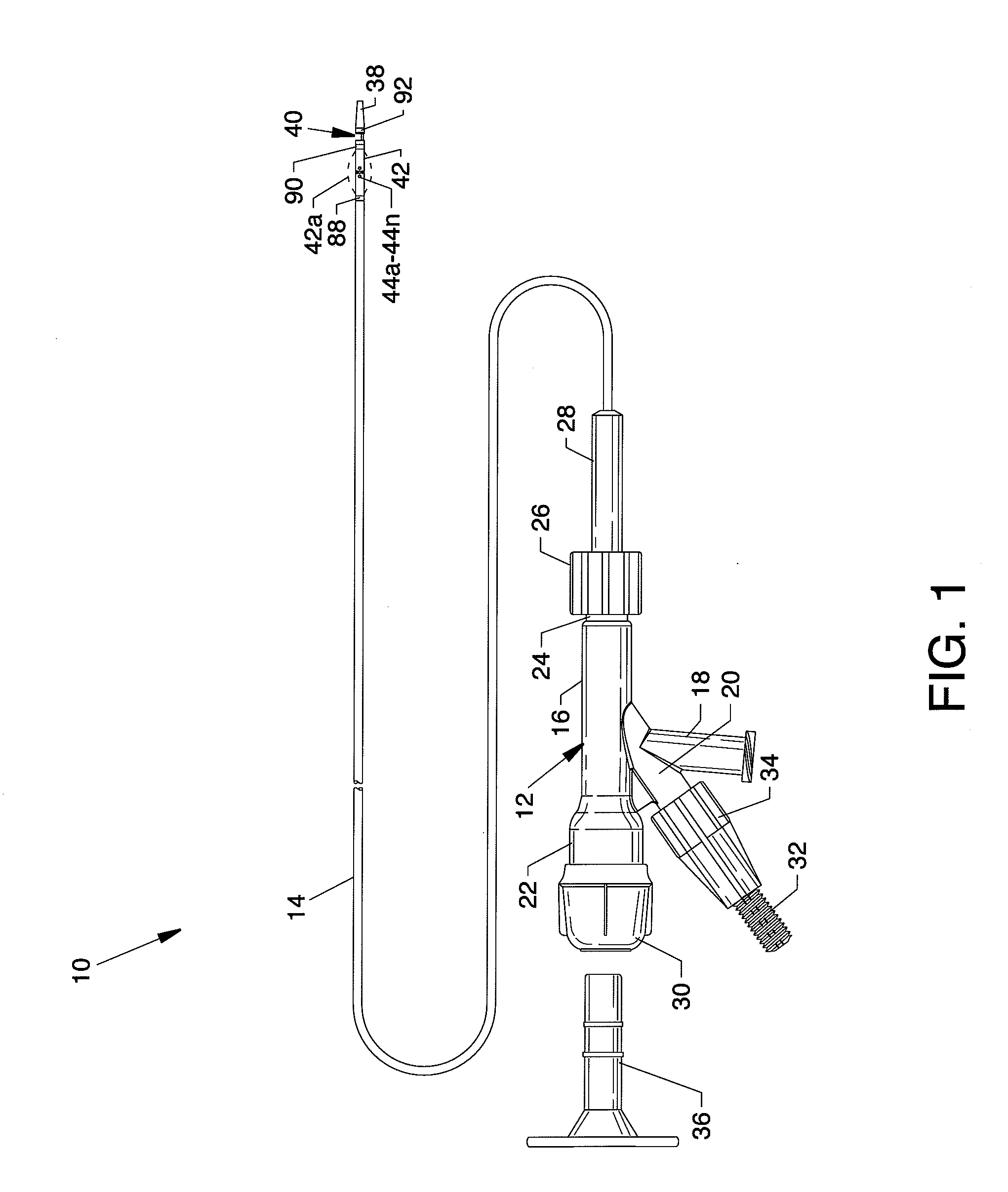
[0050]FIG. 1 is a plan view of the visible components of a rheolytic thrombectomy catheter 10. The device includes a one-piece manifold 12 having multiple structures extending therefrom or attached thereto, and also includes a flexible catheter tube 14 and other components associated therewith as described herein. The visible portion of one-piece manifold 12 includes a central tubular body 16, a threaded exhaust branch 18, and a high pressure connection branch 20 extending angularly from central tubular body 16, a partially shown cavity body 22 extending proximally from central tubular body 16 and a threaded connection port 24 extending distally from central tubular body 16. The proximal end of catheter tube 14 is secured to manifold 12 by the use of a Luer fitting 26 accommodated by threaded connection port 24. The proximal end of catheter tube 14 extends through a strain relief tube 28 and through Luer fitting 26 to communicate with manifold 12. Also shown is a hemostasis nut 30 a...


PUM


Abstract

The present disclosure involves a rheolytic thrombectomy catheter with a self-inflating proximal balloon having drug infusion capabilities. A self-inflating balloon having a plurality of outflow orifices located about the peripheral circumference thereof is located proximal to an inflow gap or orifices and a fluid jet emanator and which balloon is inflated and expanded by internal operating pressures to uniformly space and position the outflow orifices of the self-inflating balloon in close proximity to or in intimate contact with the thrombus or walls of the blood vessel. Devices of the present disclosure can be used for the purposes of thrombectomies, embolectomies, thrombus or vessel dilation and for the delivery of drugs to a thrombus or vessel site.

Description

CROSS REFERENCES TO RELATED APPLICATIONS[0001]This application claims priority from the earlier filed U.S. Provisional Application No. 61 / 009,126 filed Dec. 26, 2007, and is hereby incorporated into this application by reference as if fully set forth herein.[0002]This patent application is related to patent application Ser. No. 10 / 455,096 filed on Jun. 5, 2003, entitled “Thrombectomy Catheter Device Having a Self-Sealing Hemostasis Valve,” now U.S. Pat. No. 7,226,433.[0003]This patent application is also related to patent application Ser. No. 11 / 294,006 filed on Dec. 5, 2005, entitled “Exhaust Pressure Operated Balloon Catheter System,” which is pending.[0004]This patent application is also related to patent application Ser. No. 11 / 096,592 filed on Apr. 1, 2005, entitled “Rapid Exchange Fluid Jet Thrombectomy Device and Method,” which is pending.BACKGROUND OF THE DISCLOSURE[0005]1. Field of the Disclosure[0006]The present disclosure relates to a thrombectomy catheter, but more speci...

Claims


Application Information

Patent Timeline
IPC IPC(8): A61B17/22A61F2/958
CPCA61B17/32037A61B2017/22065A61B2017/22062
Inventor BONNETTE, MICHAEL J.THOR, ERIC J.KOZAK, DEBRA M.
Owner BOSTON SCI LTD
Why Eureka
Try Eureka