Heater warming rack

a heating rack and heater technology, applied in the field of stoves and furnaces, can solve the problems of large amount of set-up, difficult to find all three basic needs, and large structure, so as to facilitate warming or cooking foods and beverages, expand the utility of portable heaters, and support food or beverages. safety

Active Publication Date: 2012-11-06
EILERS WESTON A
View PDF29 Cites 6 Cited by
  • Summary
  • Abstract
  • Description
  • Claims
  • Application Information

AI Technical Summary

Benefits of technology

[0019]Exemplary embodiments of the present invention solve inadequacies of the prior art by providing a compact and collapsible rack that may be folded, stored and transported adjacent with, in the outline of, and supported by a portable space heater. When at a location where food warming or cooking is desired, the rack may be removed from the storage position, unfolded, and coupled to a wire grid found on the face of the portable space heater. The wire grid is commonplace in the art of portable heaters, and serves to protect against accidental contact with the heating element. The rack positively engages with this wire grid in such a way as to prevent the rack from collapsing, even when impacted with substantial force. As a result, the rack will safely support food or beverage. Owing to the placement, food or beverage is much less likely to contaminate the heating element.
[0020]A first object of the invention is to expand the utility of portable heaters having protective grids to facilitate warming or cooking foods and beverages. A second object of the invention is to provide this expanded utility with a relatively low cost rack. Another object of the present invention is to maintain the safety features of the portable heater and avoid contamination of the heating element. A further object of the invention is the provision of a rack that will couple with many diverse protective grids, allowing the rack to couple with different models and sizes of heaters without requiring change. Yet another object of the present invention is to facilitate the stowing and transport of the rack within the confines and preferably outline of the portable heater. An additional object of the invention is the provision of a rack geometry which is simple in construction, and also simple and apparent in the coupling to portable heaters.

Problems solved by technology

All three of those basic needs become much more difficult to find during winter months in areas outside of the tropics.
Many of the structures are large and bulky, and require large amounts of set-up.
While this is of less concern with permanent structures such as a residence or home, such apparatus are poorly suited for temporary use and outdoor activities such as ice fishing or camping that would require transporting and setting up the heat apparatus.
Though ideal for use in combination with a fixed stove or oven, these apparatus have not been designed to operate with a more lightweight and portable heat source.
While all are effective, they are not ideal in all environments and surroundings.
Campfires do not work when there is a higher risk of fire spreading, when there is a potential for there not being available firewood or that the firewood is wet, when in an enclosed shelter, or in other instances.
While functional, the camp stove can only be used in one function at a time, making it less convenient and less efficient.
Such an embodiment poses the distinct problem that any food drippings land on the heating element.
Additionally, such a design limits the structure to one function at a time, decreasing the usefulness of the apparatus.
Unfortunately, both such structures are similarly only functional in one capacity at a time and lack true compact portability.
In addition, while the drippings do not land on the heating elements, the grill portion is necessarily combined in the same space as the heater, posing a similar issue with odors at later points in time.
This ideal structure would be difficult to adjust during use due to the temperature of the surfaces, making it difficult to transition from using it suspended or braced at an angle to using it for cooking.
Unfortunately, the device is not transportable, limiting its application in outdoor activities.

Method used


Image

  • Heater warming rack
  • Heater warming rack
  • Heater warming rack

Examples


Embodiment Construction

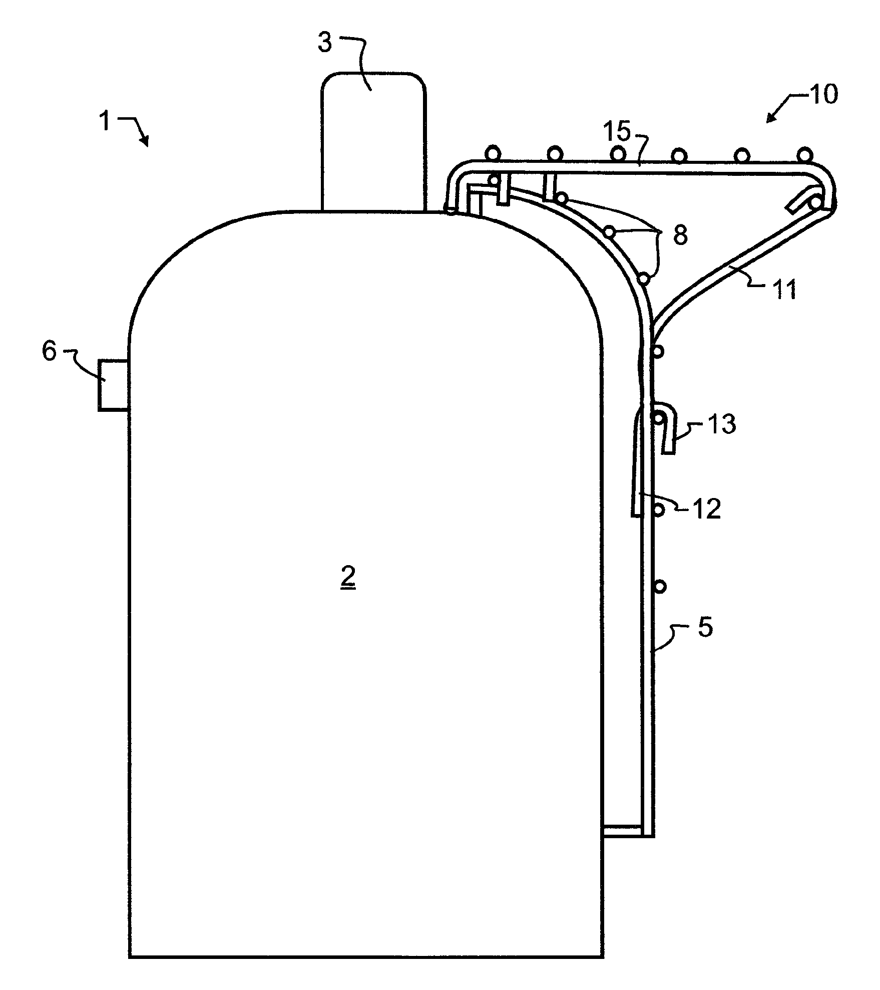
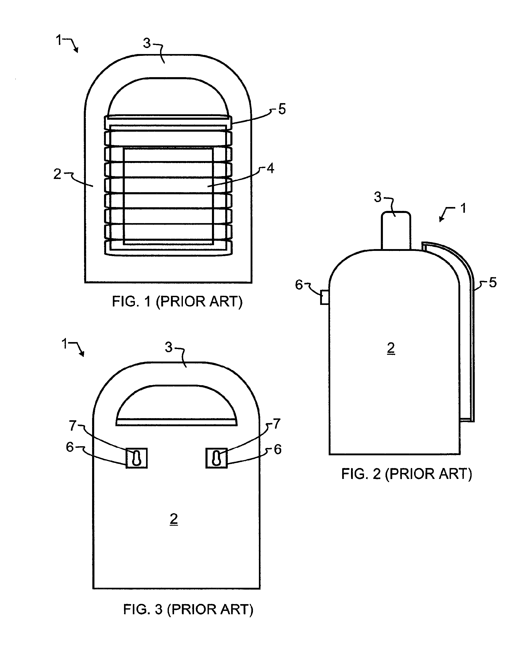
[0029]Manifested in the preferred embodiment, the present invention provides a warming rack 10 for use in combination with a prior art portable gas heater 1, such as may typically be used by outdoors enthusiasts. The specific style of space heater 1 may vary, though the most preferred prior art portable gas heater 1 is illustrated in FIGS. 1-3. Portable gas heater 1 has an upright body 2 which is readily transported by grasping handle 3, found along the top edge of body 2, and lifting. In the most preferred embodiment, portable gas heater 1 is an upright device, with heater 4 centrally located in the body 2 of the gas heater 1. As can be seen, heater 4 releases warm air and radiates heat out of the portable gas heater 1 through the side of the upright body, with a protective grid 5 preventing contact with and burns from heater 4. Protective grid 5 further prevents accidental damage to heater 4, and greatly reduces the risk of catastrophic fire.

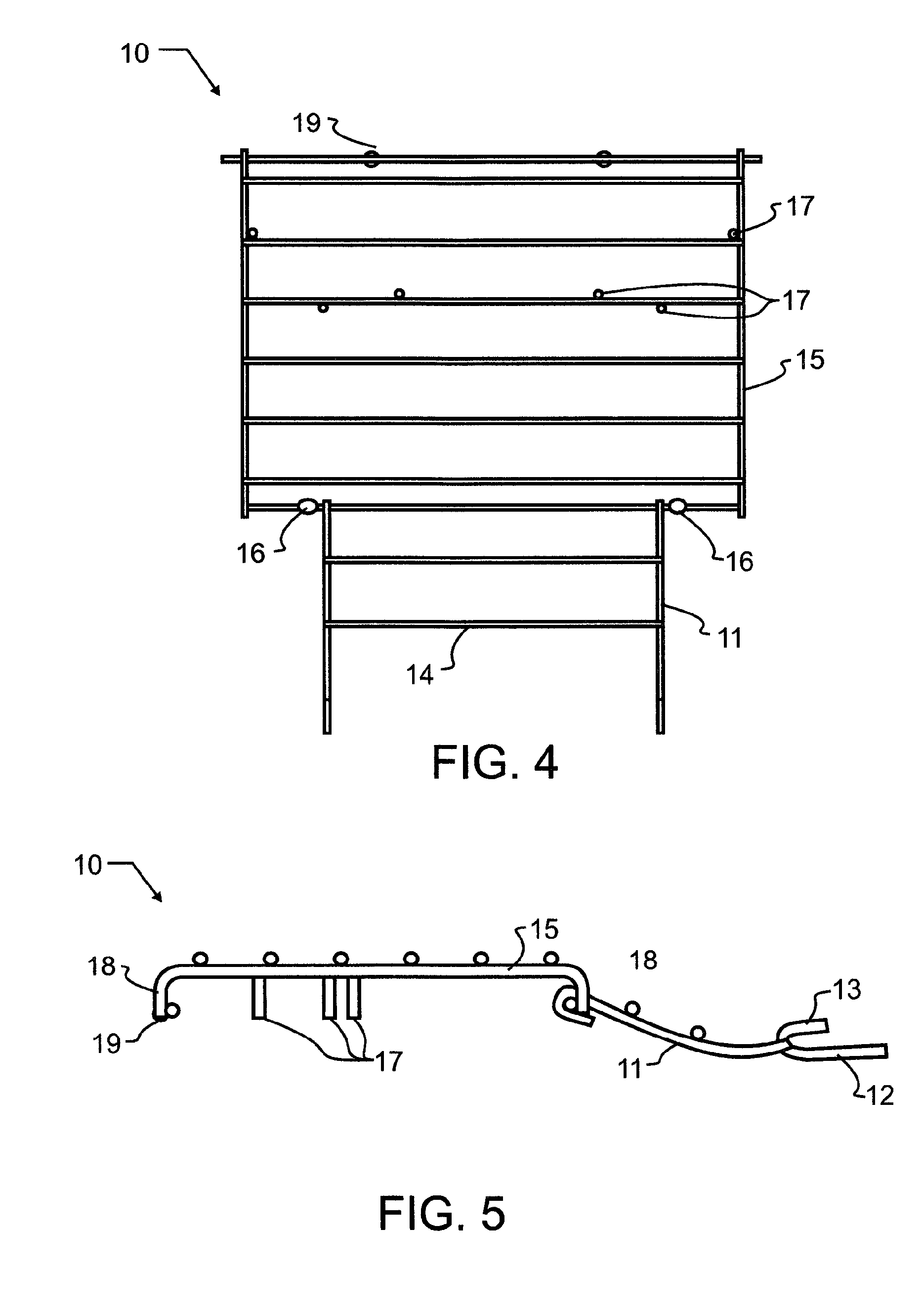
[0030]For storage purposes or for impro...


PUM


Abstract

A portable space heater is combined with a compact and collapsible rack that may be folded, stored and transported adjacent with, in the outline of, and supported by the portable space heater. The rack may be removed from the storage position, unfolded, and coupled to a protective grid found on the face of the portable space heater. The rack positively engages with this grid using bifurcated legs that swivel about a main support surface. The bifurcated legs intertwine with the protective grid in such a way as to prevent the rack from collapsing, even when impacted with substantial force. The main support surface of the rack is vertically displaced from the space heater heating element, so that food or beverage is much less likely to contaminate the heating element.

Description

BACKGROUND OF THE INVENTION[0001]1. Field of the Invention[0002]The present invention relates generally to stoves and furnaces, and more particularly to portable heating apparatus that include in combination knockdown and separable cooking and warming racks.[0003]2. Description of the Related Art[0004]Humans have several basic needs, including food, water, and a suitable environment. All three of those basic needs become much more difficult to find during winter months in areas outside of the tropics. With that in mind, humanity has found and created various forms of radiant heat, fueled by gas, electricity, wood, coal, and other sources of energy. The radiant heat has been used to warm a living space, food, water and for many other purposes.[0005]Apparatus for producing heat include but are not limited to fires, furnaces, heaters, radiators, stoves, microwaves, ovens, grills, and the like. Many of the structures are large and bulky, and require large amounts of set-up. While this i...

Claims


Application Information

Patent Timeline
Patent Type & Authority Patents(United States)
IPC IPC(8): H05B3/06
CPCA47J37/0694
Inventor EILERS, WESTON A.
Owner EILERS WESTON A
Why Eureka
Try Eureka