Method for improving the ability to recognize materials in an X-ray inspection system, and X-ray inspection system

a technology of x-ray inspection and material recognition, applied in the direction of character and pattern recognition, measurement devices, instruments, etc., can solve the problems of difficult recognition of materials situated behind one another in the beam path, the three-dimensional reconstruction of the inspection object, and the inability to determine the density, etc., to achieve the effect of improving the ability to recognize materials

Active Publication Date: 2012-11-13
SMITHS HEIMANN
View PDF18 Cites 5 Cited by
  • Summary
  • Abstract
  • Description
  • Claims
  • Application Information

AI Technical Summary

Benefits of technology

[0007]It is therefore an object of the invention to provide a method that improves the ability to recognize materials in an X-ray inspection system.
[0028]In an embodiment of the invention, the weighting factors in the calculation of the synthetic image depend on the position of the pixel in the X-ray image. Accordingly, wm=wm(x,y) holds true, with x and y being the coordinates of a pixel in the image. By way of example, this affords the possibility of suppressing the contours of items made of different materials in various regions of the synthetic image using different weighting factors and thus affords the possibility of detecting a plurality of materials to be recognized in a synthetic image.
[0029]The absorption caused by a layer during the calculation of the synthetic image is preferably colored as a function of the assumed material of the layer. The coloring is preferably brought about based on the atomic number Z of the material. Thus, for example, metallic materials are colored blue and organic materials are colored orange. This coloring affords simpler detection of the sought after materials by the operating staff of the X-ray inspection system.

Problems solved by technology

Hence, a three-dimensional reconstruction of the inspection object, required for determining the density, cannot be achieved.
Therefore, materials situated behind one another in the beam path cannot be easily recognized.

Method used


Image

  • Method for improving the ability to recognize materials in an X-ray inspection system, and X-ray inspection system
  • Method for improving the ability to recognize materials in an X-ray inspection system, and X-ray inspection system
  • Method for improving the ability to recognize materials in an X-ray inspection system, and X-ray inspection system

Examples


Embodiment Construction

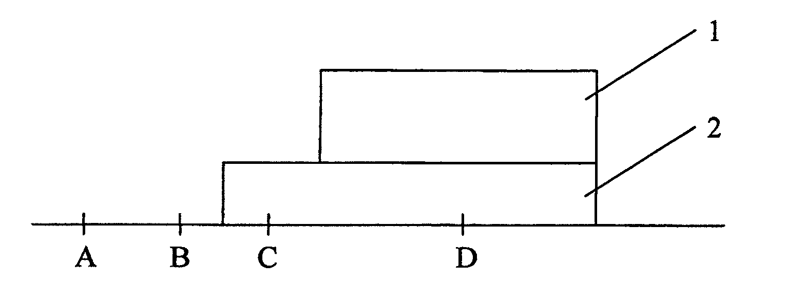
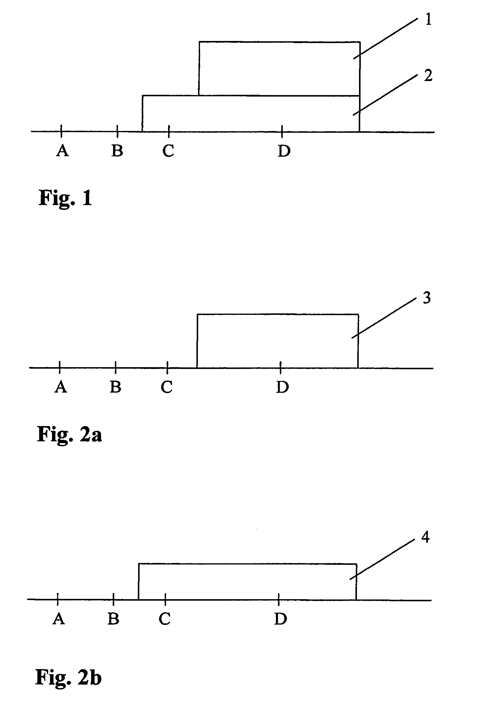
[0039]FIG. 1 illustrates a schematic sectional illustration of an object to be examined that is composed of two materials. Material 1 is the plastic explosive Semtex; material 2 is iron. The thickness of material 1 is 1.5 mm; the thickness of material 2 is 1 mm. Four positions A, B, C and D, where X-ray detectors are arranged, are highlighted in an exemplary fashion. When an absorption X-ray image is recorded, there is no material between the (not illustrated) X-ray source in an X-ray inspection system and the X-ray detectors at positions A and B, there is only material 2 between the X-ray source and the detector at position C and both material 1 and material 2 between the X-ray source and the X-ray detector at position D. The X-ray detectors detect the X-ray radiation emitted by the X-ray source and attenuated by the object.

[0040]In a dual-energy X-ray inspection system, two absorption X-ray images of the object are recorded at two different energy spectra of the X-ray radiation. I...


PUM


Abstract

A method for improving the ability to recognize materials in an X-ray inspection system is provided that includes the steps of recording at least two absorption X-ray images of an object to be examined at different energies, mathematically modeling the object by a number of layers assuming a particular material for each layer, wherein an absorption value describes the absorptivity of a layer, the number of layers is less than or equal to the number of X-ray images and at least one layer is assumed to be a material to be recognized during the inspection, decomposing the absorption value of each layer into a path-dependent factor and an energy-dependent factor, calculating the path-dependent factors for all layers from the absorption X-ray images using the absorption equation, calculating at least one synthetic image from the sum of all layers of the product of the absorption values and the weighting factors, evaluating the synthetic image.

Description

[0001]This nonprovisional application is a continuation of International Application No. PCT / EP2008 / 006344, which was filed on Aug. 1, 2008, and which claims priority to German Patent Application No. DE 10 2007 042 144.5, which was filed in Germany on Sep. 5, 2007, and which are both herein incorporated by reference.BACKGROUND OF THE INVENTION[0002]1. Field of the Invention[0003]The present invention relates to a method for improving the ability to recognize materials in an X-ray inspection system, and to an X-ray inspection system.[0004]2. Description of the Background Art[0005]It is known that in order to inspect objects, in particular pieces of luggage, in respect of suspicious contents, X-ray inspection equipment is used in which the objects to be inspected are irradiated by X-ray beams. For this, the X-ray inspection equipment has an X-ray source and detectors in which the intensities of the attenuated radiation are detected. Brightness values for a two-dimensional X-ray image ...

Claims


Application Information

Patent Timeline
Patent Type & Authority Patents(United States)
IPC IPC(8): G06K9/00
CPCG01N23/087
Inventor SIEDENBURG, UWE
Owner SMITHS HEIMANN
Why Eureka
Try Eureka