Biopsy tissue marker

a tissue marker and biopsy technology, applied in the field of surgical devices, can solve the problems of difficult or impossible identification, significant reduction of the mortality rate caused by this form of cancer,

Active Publication Date: 2012-11-13
CR BARD INC
View PDF517 Cites 22 Cited by
  • Summary
  • Abstract
  • Description
  • Claims
  • Application Information

AI Technical Summary

Problems solved by technology

Proper diagnostic procedures, frequent examination by well known techniques such as “mammography” and prompt subsequent surgical treatment have, however, significantly reduced the mortality rate caused by this form of cancer.
Placement of a marker can be an important step to take since most abnormalities biopsied are small or subtle and can become extremely difficult or impossible to identify after a core biopsy procedure.

Method used


Image

  • Biopsy tissue marker
  • Biopsy tissue marker
  • Biopsy tissue marker

Examples


Embodiment Construction

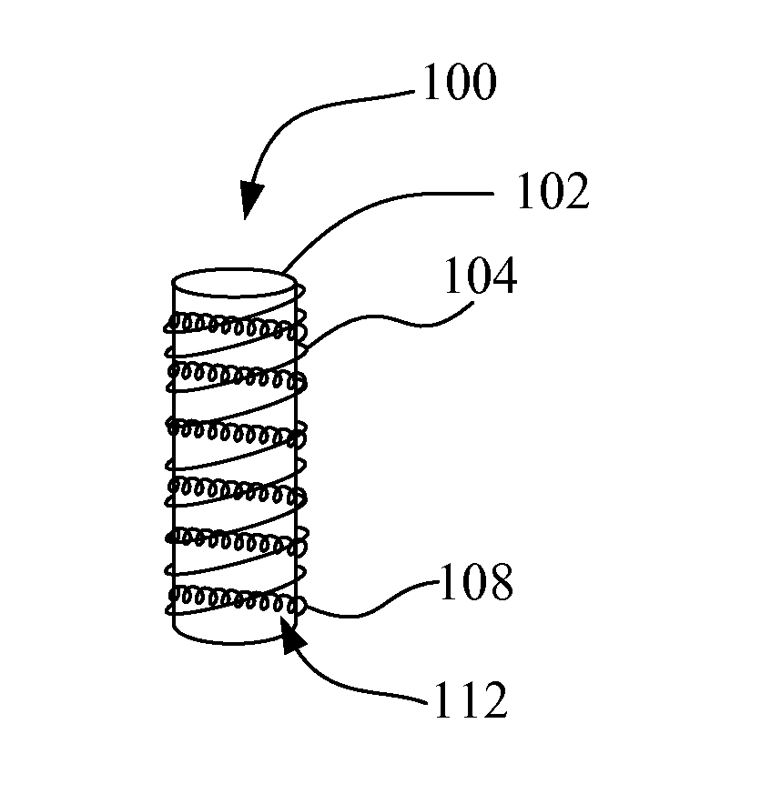
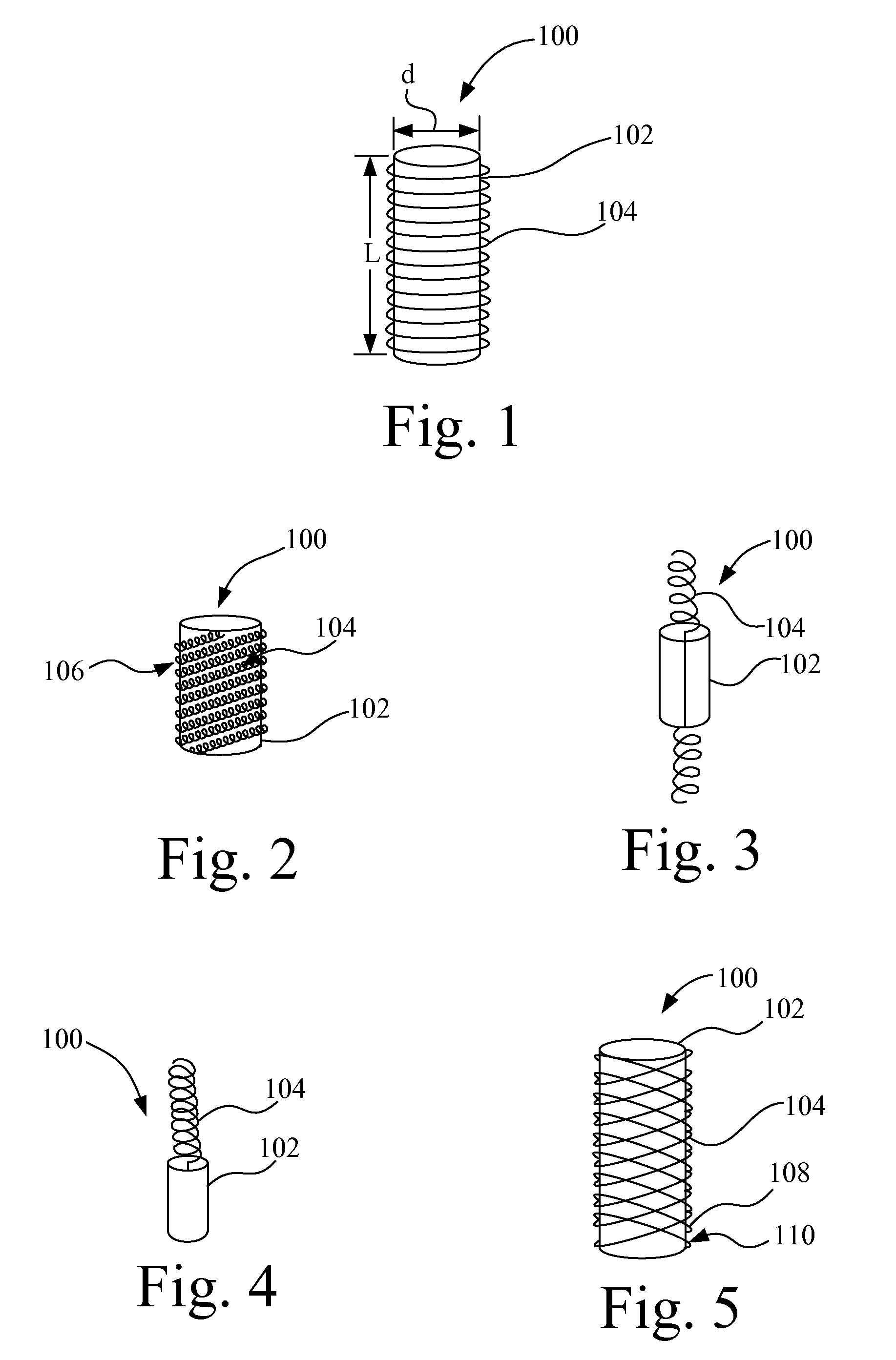
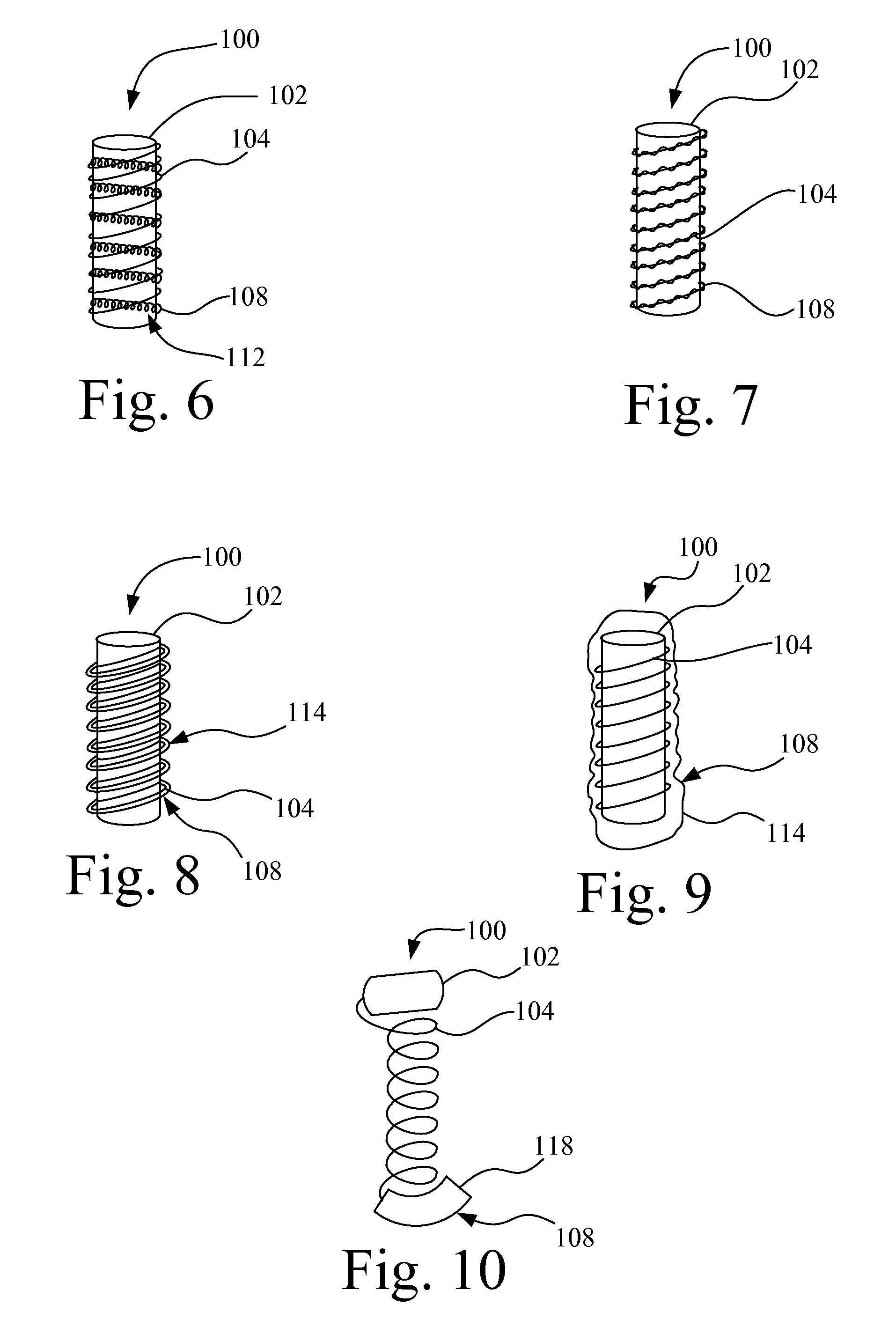
[0022]Referring to FIGS. 1, 2, 3, 4, 5, 6, 7, 8, 9, and 10, a biopsy site marker is shown and is generally designated 100. The biopsy site marker 100 includes a first marker element 102 having a cylindrical shape or contour. The cylindrical shape or contour can fill the void of the biopsy cavity after the tissue sample is removed during the biopsy process.

[0023]In more particularity, and as seen in FIG. 1, a cylindrical shape or contour is generally defined by a discrete segment of a body having a diameter (d) and a length (L). The cylindrical shape has a cross-section that is curved. In an embodiment, the length is greater than the diameter. In an embodiment, and as seen in FIG. 1, the length of the cylindrical shape may be straight. In another embodiment, the length of cylindrical shape may be curved. In an embodiment, the cylindrical shape is generally solid. The biopsy site marker 100 may be made of a polymer, metal, or ceramic material and is generally proportioned to enable im...


PUM


Abstract

A biopsy site marker is disclosed. The biopsy site marker includes a first marker element and a second marker element. The first marker element is configured for detection by a first imaging modality. The second marker element is configured for detection by a second imaging modality different from the first imaging modality. The second marker element may be a non-absorbable wire having a predetermined shape and is substantially engaged with the first marker element.

Description

CROSS REFERENCE TO RELATED APPLICATIONS[0001]This application is a U.S. national phase of International Application No. PCT / US2009 / 031688, filed Jan. 22, 2009, based upon U.S. Provisional Patent Application Ser. No. 61 / 025,128, filed Jan. 31, 2008, from which priority is claimed.FIELD OF THE INVENTION[0002]The present invention relates generally to surgical devices, and more specifically, to biopsy tissue markers.BACKGROUND[0003]In modern medical practice small tissue samples, known as biopsy specimens, are often removed from tumors, lesions, organs, muscles and other tissues of the body. The removal of tissue samples may be accomplished by open surgical technique, or through the use of a specialized biopsy instrument such as a biopsy needle, including vacuum assisted biopsy devices.[0004]After a tissue sample has been removed, it is typically subjected to diagnostic tests or examinations to determine cytology, histology, presence or absence of chemical substances that act as indica...

Claims


Application Information

Patent Timeline
Patent Type & Authority Patents(United States)
IPC IPC(8): A61B19/00
CPCA61B19/54A61B2019/5408A61B2019/5425A61B2019/5454A61B90/39A61B2090/3908A61B2090/3925A61B2090/3954
Inventor RANPURA, HIMANSHU M.
Owner CR BARD INC
Why Eureka
Try Eureka