
Artificial respiration device for patients suffering from hypoxemia or anoxemia

a technology of artificial respiration and patient, which is applied in the direction of respirator, respiratory mask, trachea tube, etc., can solve the problems of difficult to ensure patient safety against excessive dilation (and even bursting) of the airways

Active Publication Date: 2012-11-20
BOUSSIGNAC GEORGES
View PDF16 Cites 2 Cited by
  • Summary
  • Abstract
  • Description
  • Claims
  • Application Information

AI Technical Summary

Benefits of technology

"The present invention is an improvement of a respiratory assistance device that can be used safely as an artificial respiration device to treat hypoxemia or anoxemia. The device includes a tubular element with auxiliary channels that supply respiratory gas, which open into the main channel of the device. The device also has deflecting means to ensure that the jets of respiratory gas meet in the main channel and do not harm the patient. The invention includes a lateral safety orifice that allows the downstream part of the main channel to communicate with the outside air, and a conduit to connect the orifice to the ambient air. The device may also have protruding internal obstacles to prevent sealing by an external object. The invention improves safety and comfort for patients during respiratory assistance therapy."

Problems solved by technology

With such high flow rates of respiratory gas, however, it is difficult to ensure patient safety against excessive dilation (and even bursting) of the airways in the event of accidental occlusion of the proximal end of said main channel.

Method used


Image

  • Artificial respiration device for patients suffering from hypoxemia or anoxemia
  • Artificial respiration device for patients suffering from hypoxemia or anoxemia
  • Artificial respiration device for patients suffering from hypoxemia or anoxemia

Examples


Embodiment Construction

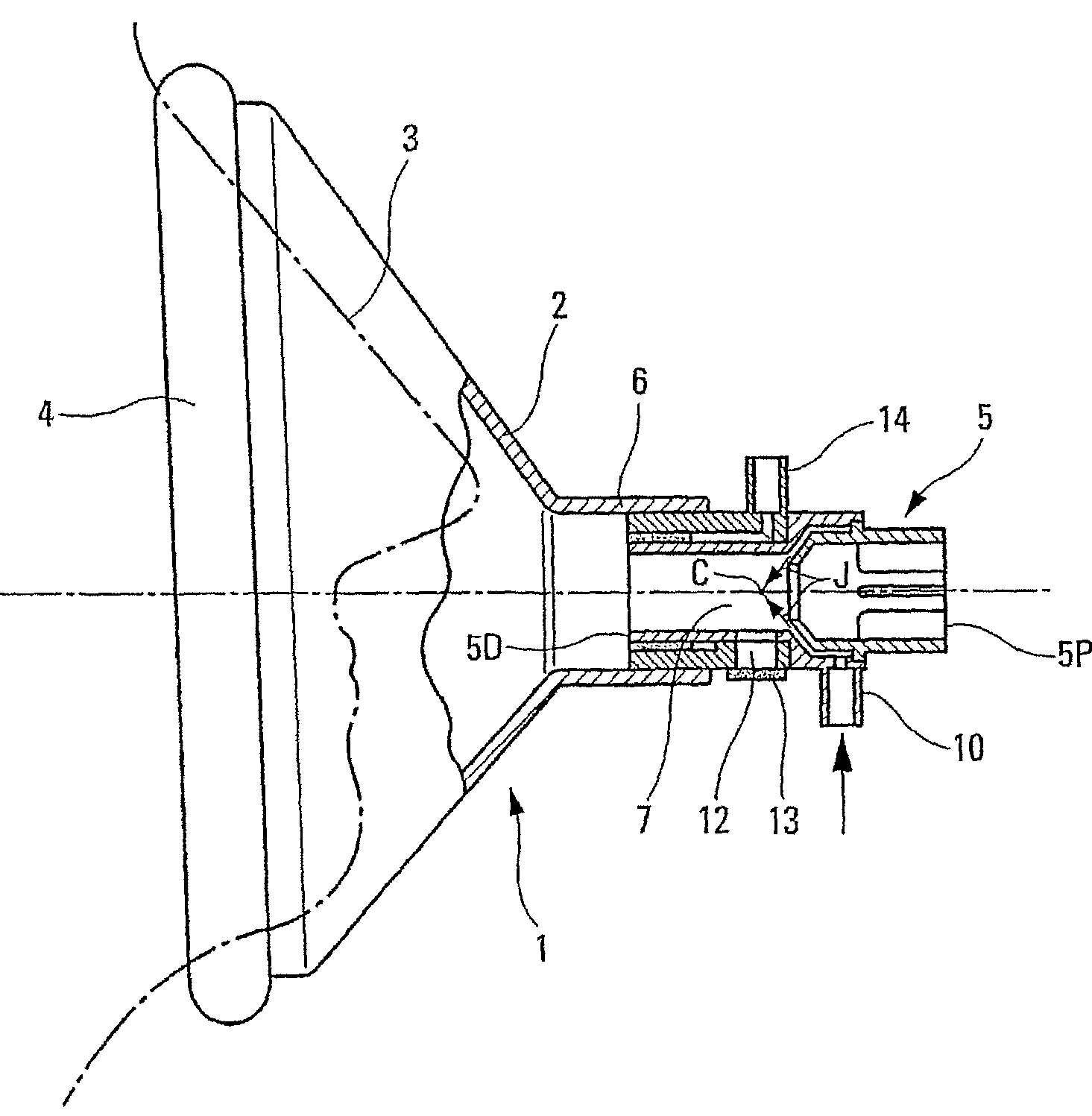
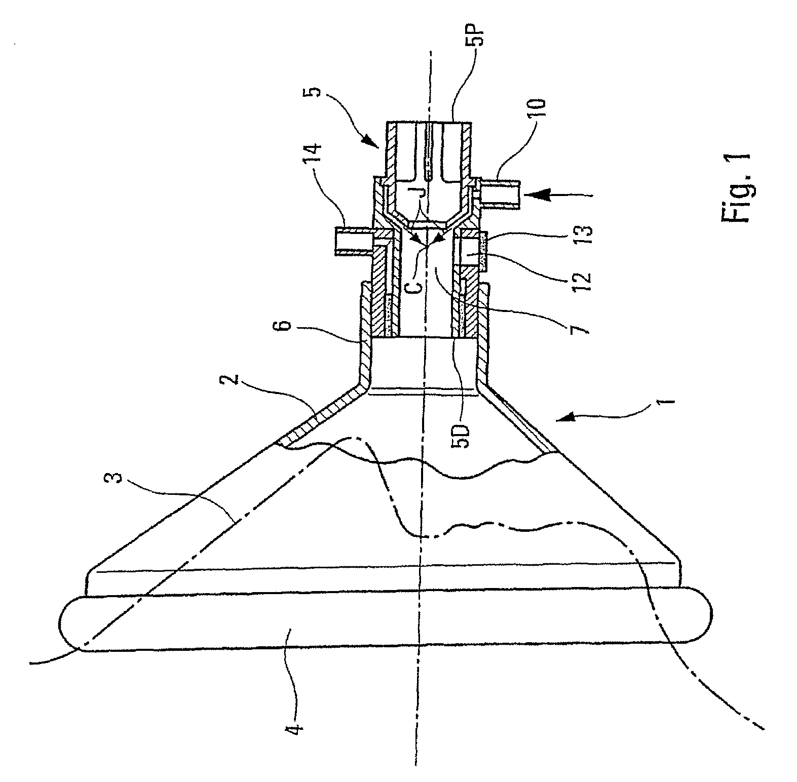
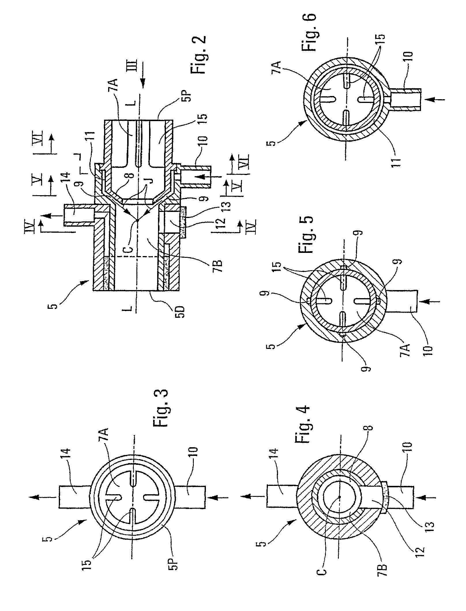
[0023]As is shown in more detail in FIGS. 2 to 6, the tubular element 5 forms an internal main channel 7 and it comprises, in the middle part, deflecting mean 8 directed toward the axis L-L of said channel 7. The purpose of the deflecting means 8 is to ensure that the jets of respiratory gas J injected via peripheral auxiliary channels 9 are deflected in the direction of said axis of the main channel 7, said peripheral auxiliary channels 9 being supplied from an inlet connector piece 10 by way of a peripheral annular chamber 11, and said jets of respiratory gas thus converging toward a point of convergence C of the axis L-L of said main channel 7.

[0024]Said deflecting means 8 thus divide the main channel 7 into an upstream part 7A, which is arranged at the proximal end 5P of the tubular element 5, and a downstream part 7B, in which the point of convergence C is situated and which is arranged at the distal end 5D of said tubular element 5.

[0025]According to the main feature of the pr...


PUM


Abstract

Disclosed is an artificial respiration device that includes a tubular element, which forms a main channel having an upstream part at the proximal end of the tubular element and a downstream part at the distal end of the tubular element. Auxiliary channels open into the main channel and deflecting means are located internal to the main channel. The deflecting means are configured to deflect jets of respiratory gas injected into the main ckannel through the auxiliary channels so as to converge the gas at a point of convergence inside the main channel. The tubular element also includes at least one lateral safety orifice that extends through a lateral wall of the tubular element at a location sustantially opposite the point of convergence, and which is configured to communicate air from outside the tubular element to the downstream part of the main channel.

Description

FIELD OF THE INVENTION[0001]The present invention relates to an artificial respiration device that can be used on patients suffering from conditions causing hypoxemia or anoxemia, for example cardiac arrest, pulmonary edema, severe acute respiratory syndrome, avian flu, etc.BACKGROUND OF THE INVENTION[0002]European patents EP-0 390 684 and EP-0 911 051, for example, disclose a tubular respiratory assistance device which forms a main channel and which is designed to be connected via its distal end to an airway of a patient, such that said main channel connects the respiratory system of said patient to the outside, said device comprising auxiliary channels that are connected to deflecting means for injecting convergent jets of respiratory gas deflected toward the inside of said main channel.[0003]A respiratory assistance device of this kind is used particularly on patients whose spontaneous respiration is insufficient, said deflected jets of respiratory gas allowing said patients to b...

Claims


Application Information

Patent Timeline
Patent Type & Authority Patents(United States)
IPC IPC(8): A61M16/12
CPCA61M16/04A61M16/06A61M16/12A61M16/127A61M16/085A61M16/0858A61M2205/42A61M2205/276A61M16/08
Inventor BOUSSIGNAC, GEORGES
Owner BOUSSIGNAC GEORGES
Learn More