Diverter valve

a technology of diverter valve and valve body, which is applied in the direction of multiple-way valve, transportation and packaging, mechanical equipment, etc., can solve the problems of affecting the aesthetics of the tub filler, requiring a significant amount of force to actuate the diverter, and the current diverter used with this type of shower mixer can achieve the effect of reducing reducing the activation force, and reducing the waist of the cross sectional area

Active Publication Date: 2012-11-20
KOHLER CO
View PDF27 Cites 7 Cited by
  • Summary
  • Abstract
  • Description
  • Claims
  • Application Information

AI Technical Summary

Benefits of technology

[0013]The stem includes a downstream portion that has a reduced cross sectional area relative to an upstream portion of the stem. The stem is configured and positioned such that the reduced cross sectional area helps reduce the activation force needed to move the stem from the first position to the second position.
[0014]In preferred forms the housing also houses a mixing valve suitable to control both temperature and volume, the stem tapers radially inwardly from the upstream portion to the downstream portion, the stem also flares radially outwardly downstream of the downstream portion, and the upstream portion is essentially cylindrical. In other forms the stem is linked to a seal coupled to the upstream portion, there is a biasing member (e.g. a spring) urging the stem towards the first position, and a stop member is provided to help capture the compression spring.
[0016]The diverter stem has an upstream portion, a downstream portion, and a reduced cross sectional waist between the upstream and downstream portions. The waist tapers radially inwardly from the upstream portion and flares radially outwardly towards the downstream portion. Thus, the diverter stem is configured and positioned such that the reduced cross sectional area helps reduce the activation force needed to move the stem from the first position to the second position.
[0017]It will be appreciated that these embodiments provide a diverter valve requiring a reduced activation force to move the diverter from the non-diverted to the diverted position. This is achieved at low cost and in a reliable manner. This not only helps comply with governmental regulations, it provides the device with a usage feel that gives the impression of a well constructed device.

Problems solved by technology

While this type of filler mounted diverter assembly serves the basic functional needs, it disrupts the aesthetics of the tub filler somewhat.
Further, diverters of this type can accidentally snag nearby items.
However, current diverters used with this type of shower mixer can require a significant amount of force to actuate the diverter.
For arthritic or otherwise disabled persons even this can be painful or difficult.
However, the user is required to overcome a significant amount of spring force to manipulate the diverter.
Architects and building owners are therefore becoming increasingly reluctant to specify products which present this type of problem.

Method used


Image

  • Diverter valve
  • Diverter valve
  • Diverter valve

Examples


Embodiment Construction

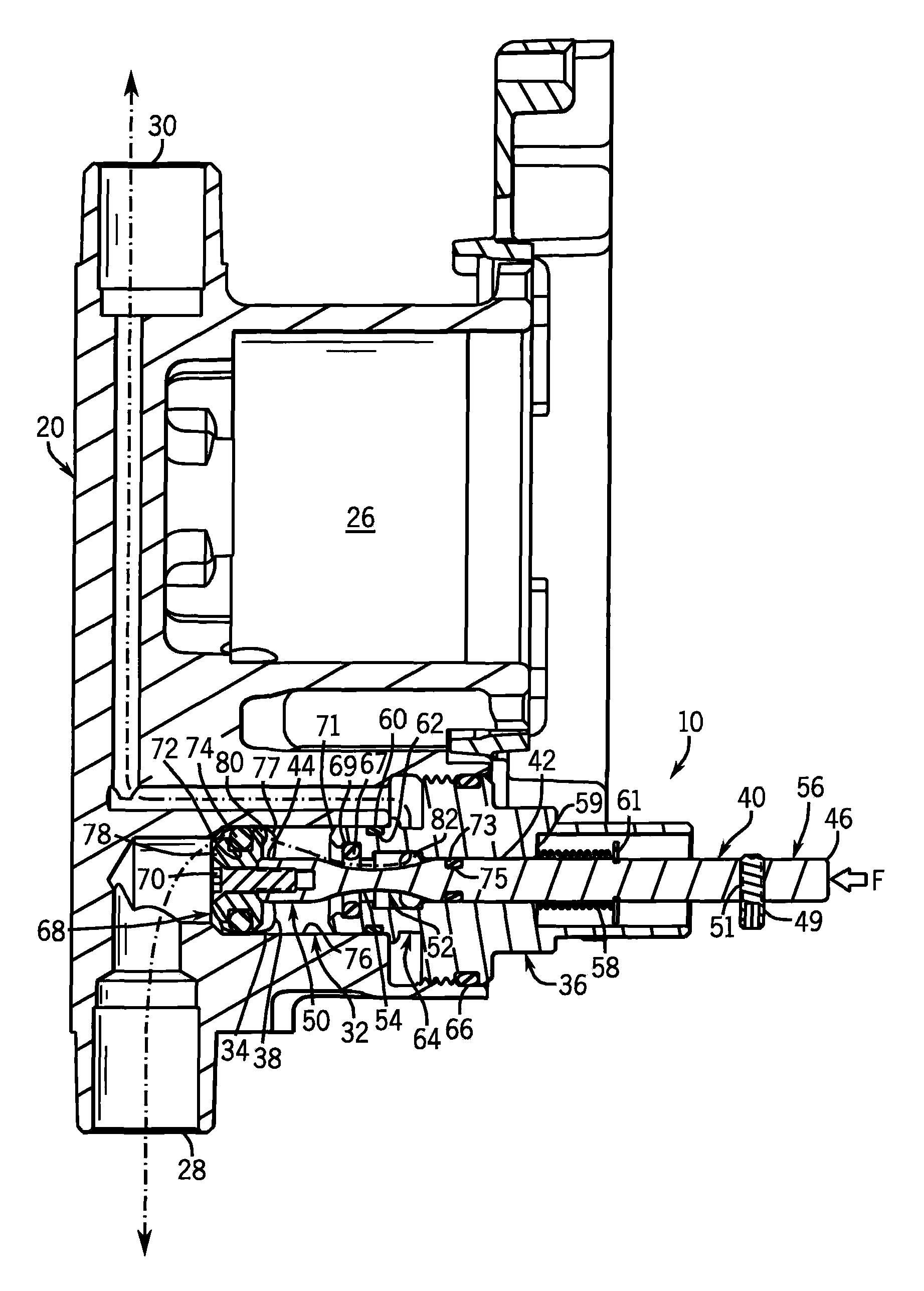
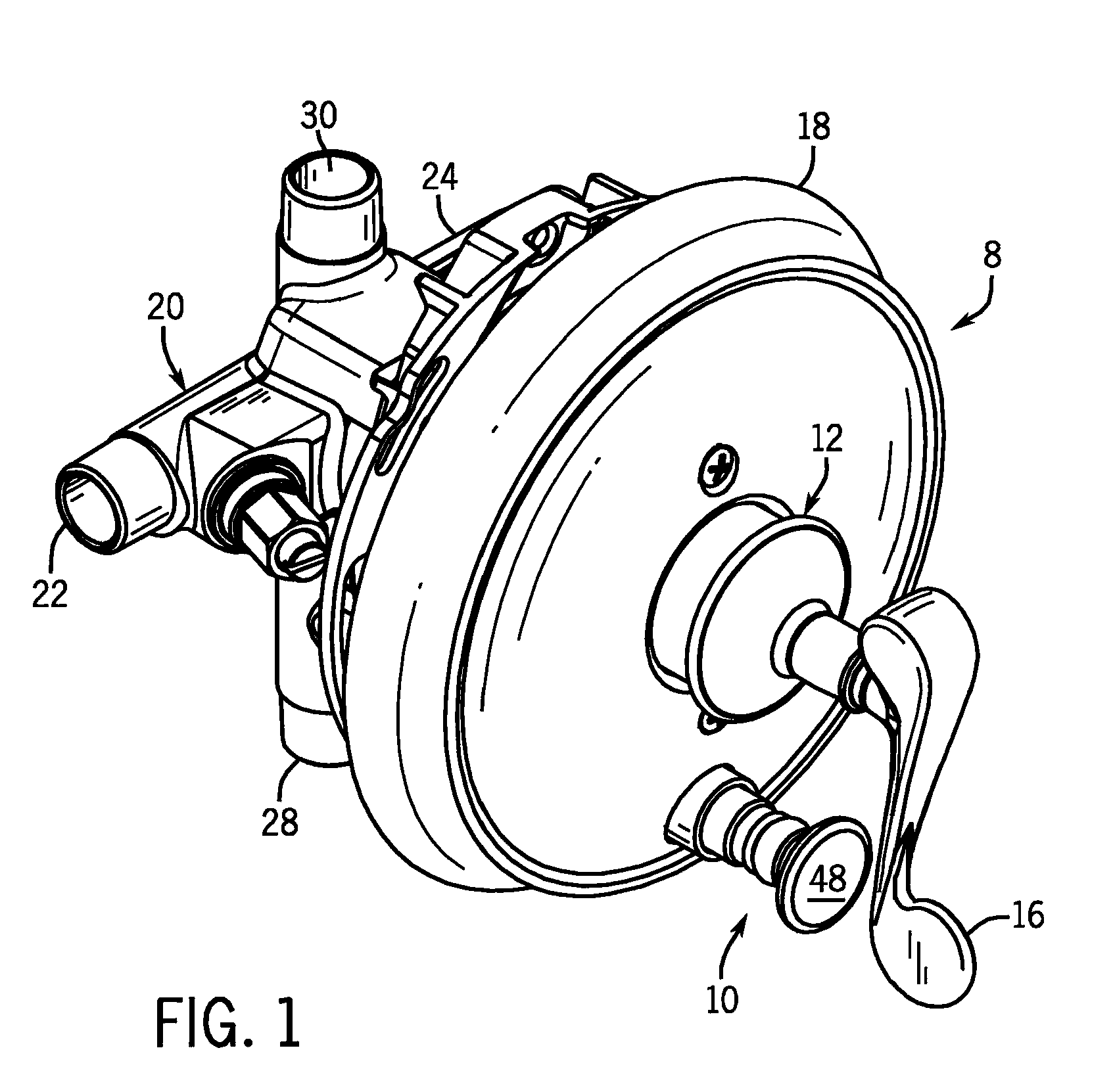
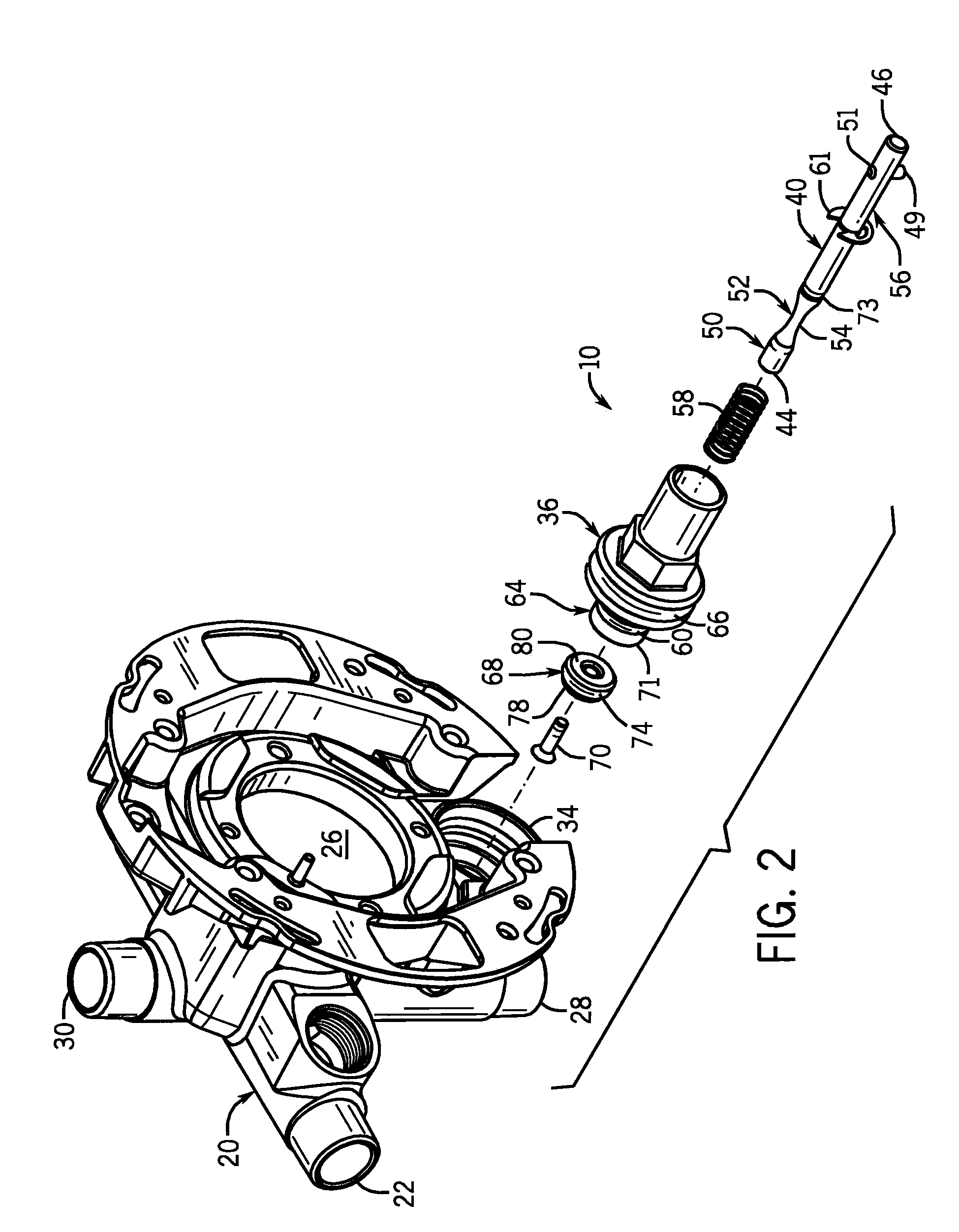
[0025]FIG. 1 shows a shower mixer generally 8 having a diverter valve 10, a mixing valve 12, a handle 16 for rotating the control components of the mixing valve, and a decorative escutcheon 18. The mixing valve 12 is received in a mixing cavity 26 of the main housing 20. That housing receives a hot water supply into conduit 22 and a cold water supply into conduit 24.

[0026]Water leaving the housing 20 either leaves via outlet 28 (per FIG. 4) or outlet 30 (per FIG. 6). The mixing valve 12 is preferably of a conventional type where rotating the handle 16 controls both temperature and volume (e.g. increasing rotation starts a cold volume, which then increases to a maximum cold volume, which then blends to create a hotter flow).

[0027]The specific type of mixing valve is not critical. Further, the mixer need not be for use with a tub / shower combination. Instead, it could control flow between a main faucet and a spray head, or between a main faucet and a pot filler.

[0028]Mixing cavity 26 i...


PUM


Abstract

A diverter valve is disclosed for use in a shower mixer valve or the like. It is constructed to reduce the force needed to be applied by the bather to actuate the diversion. There is a diverter stem that is moveable between a non-diverted and diverted position. The diverter stem includes an upstream portion and a reduced cross sectional waist portion downstream of the upstream portion. The reduced portion interacts with the diverted fluid to reduce the force required to move the diverter stem from the non-diverted to the diverted position.

Description

CROSS-REFERENCE TO RELATED APPLICATION[0001]Not applicableSTATEMENT OF FEDERALLY SPONSORED RESEARCH OR DEVELOPMENT[0002]Not applicableBACKGROUND OF THE INVENTION[0003]The present invention relates to fluid control valves which can divert flow between / among multiple outlet fittings. More particularly it relates to structures used therewith which reduce the needed diverter activation force.[0004]Most bath tub / shower combinations have a tub filler spout positioned about two feet above the tub floor, and a separate showerhead positioned about six feet above the tub floor. A single mixing valve controls the temperature and rate of flow of the water for both. There is often a diverter unit positioned directly on the tub filler spout. All flow from the control valve will normally go to the filler spout (and thus the tub). However, when the diverter is activated essentially all flow will be directed up to the showerhead.[0005]While this type of filler mounted diverter assembly serves the ba...

Claims


Application Information

Patent Timeline
Patent Type & Authority Patents(United States)
IPC IPC(8): F16K11/16F16K11/07F16K1/42
CPCE03C1/023F16K11/0445Y10T137/2685Y10T137/86831Y10T137/86879Y10T137/86992
Inventor NIVER, MICHAEL A.
Owner KOHLER CO
Why Eureka
Try Eureka