
Screen device

a screen and screen mounting technology, applied in the direction of screen/movable grille, insect protection, door/window protection devices, etc., can solve the problems of large width in the direction of sliding movement of the screen mounting frame, impaired screen device functions such as the light blocking effect and the insect-proof property, and impaired opening and closing operation, so as to prevent the effect of enhancing the surface strength of the screen or the like from interfering with the vertical rails, stably realized, and reinforced the surface strength of the screen

Active Publication Date: 2012-11-27
METACO INC
View PDF27 Cites 7 Cited by
  • Summary
  • Abstract
  • Description
  • Claims
  • Application Information

AI Technical Summary

Benefits of technology

The present invention provides a screen device that can be used as a curtain, a blind, a screen window, and a partition, and can smoothly and stably open and close. The screen device includes a pair of screen mounting frames that are arranged so as to oppose each other and at least one of which is slidable, a screen mounted between the frames, and a pair of sliding guide frames disposed near the ends of the screen. The sliding guide frames are flexuous and have a free end, allowing for easy storage and pulling out. The screen device can be manufactured to different sizes for different openings. The invention solves the problem of deflection of the screen due to wind pressure and ensures smooth and stable operation.

Problems solved by technology

However, the following problems are pointed out specifically in the case where the width in the opening and closing direction, that is, the width in the direction of sliding movement of the screen mounting frame is large.
When the screen is significantly deflected in this manner, a large gap is generated with respect to the sliding guide frame, and hence the functions of the screen device such as the light blocking effect and the insect-proof property are impaired.
However, when the screen is deflected significantly as described above, the support by the screen is insufficient, and hence the upper sliding guide frame is deflected by its own weight, whereby the opening and closing operation of the screen device is impaired.
However, since the cantilever does not have a function to restrain the deflection due to the wind pressure of the screen, other technical means is required in order to solve the above-described problem caused by the deflection of the screen due to the wind pressure drastically.

Method used


Image

  • Screen device
  • Screen device
  • Screen device

Examples


Embodiment Construction

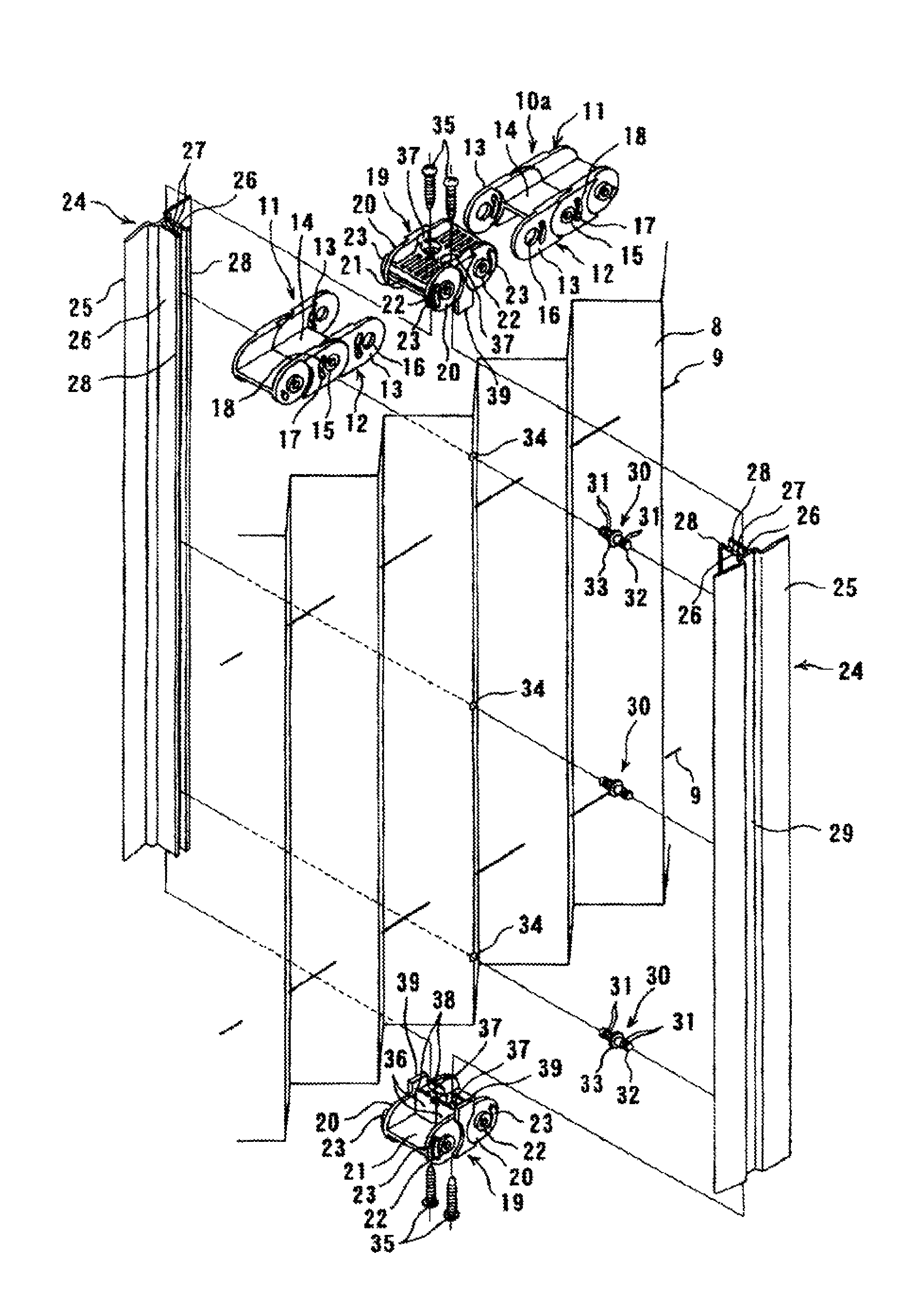
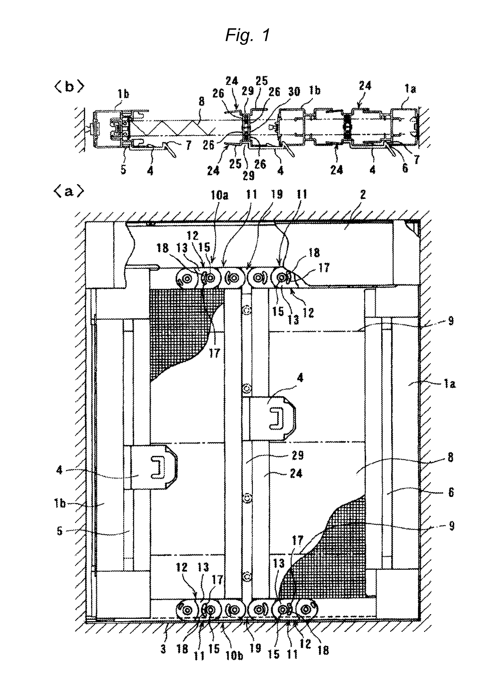
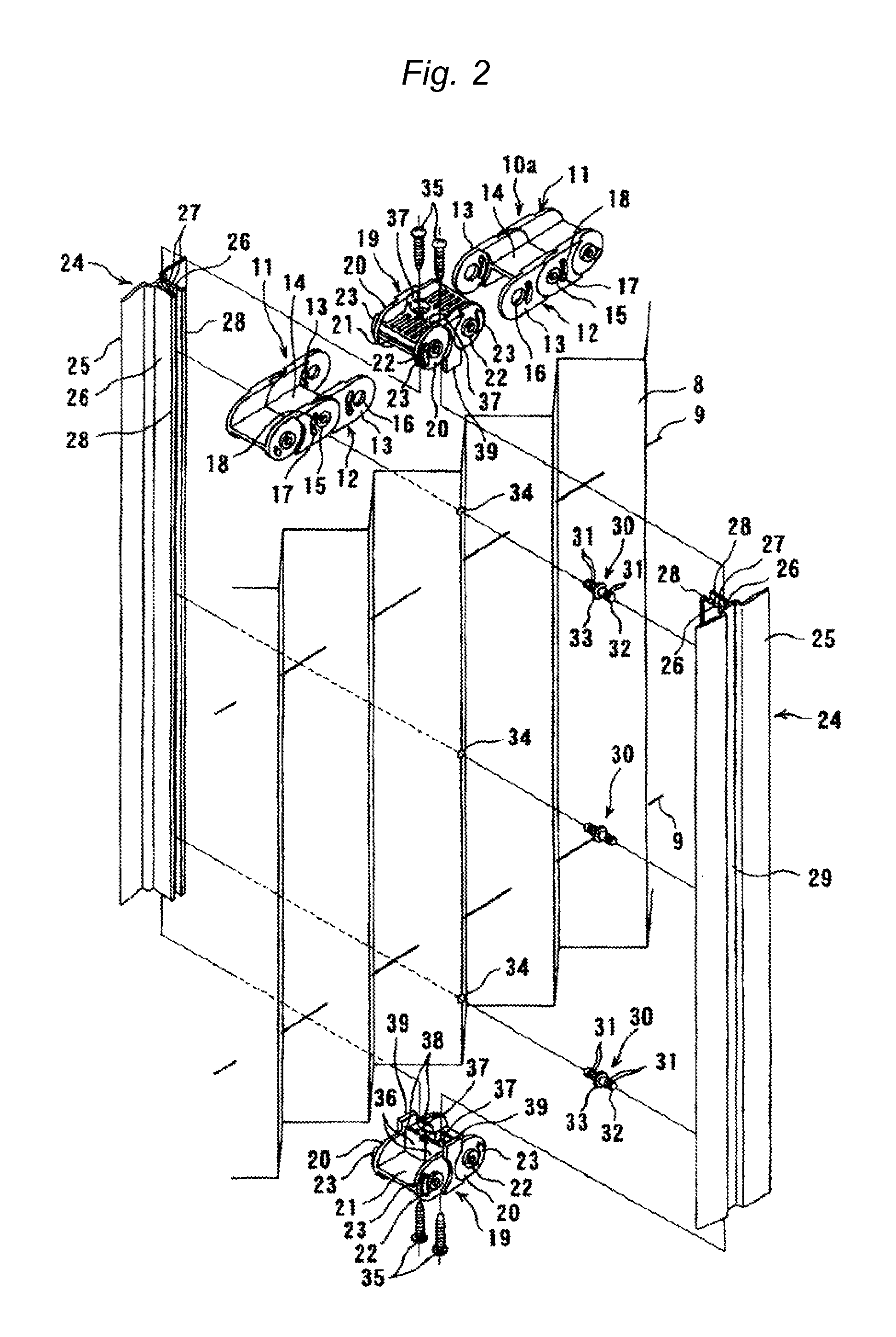
[0022]FIGS. 1(a) and (b) are a front view showing an embodiment of a screen device according to the present invention and a cross-sectional view of an upper portion thereof respectively. FIG. 2 is an exploded perspective view of principle portions showing a peripheral part of vertical rails of the screen device shown in FIGS. 1(a) and (b).

[0023]The screen device shown in FIGS. 1(a) and (b) and FIG. 2 includes a pair of screen mounting frames 1a, 1b. The screen mounting frame la is fixed to the right side of an inner edge of an opening, while the screen mounting frame 1b is disposed so as to be slidable in the lateral direction of the opening toward the left side of the inner edge of the opening. The both screen mounting frames 1a, 1b are opposed to each other. An upper rail 2 is disposed on the upper side of the inner edge of the opening along the lateral direction of the opening, and upper end portions of the screen mounting frames 1a, 1b are stored inside the upper rail 2. A lower...


PUM


Abstract

In a screen device, a pair of vertical rails 24 arranged on the front and back sides of a screen 8 so as to oppose to each other are connected by connecting members 30 and are fixed between a pair of sliding guide frames 10a and 10b with the intermediary of the screen. The connected vertical rails are integrally slidable in the direction parallel to the direction of sliding movement of a screen mounting frame, so that the screen is restrained from being deflected even when it receives a wind pressure in the closed state when the width in the opening and closing direction is large.

Description

TECHNICAL FIELD[0001]The present invention relates to a multi-purpose screen device which can be used as a curtain, a blind, a screen window, and a partition.BACKGROUND ART[0002]As a device which resolves constraints on installation when being used as light blocking and light adjusting means such as a curtain or a blind or as a screen window or a partition and realizes smooth and stable opening and closing operation, the applicant of the present invention provides a screen device (for example, Patent Document 1).[0003]In the screen device disclosed in Patent Document 1, a screen is mounted to one of a pair of screen mounting frames, which are arranged so as to oppose to each other and at least one of which is slidable, so as to allow free contraction and expansion between the both screen mounting frames, and a pair of sliding guide frames are disposed near both end portions of the screen, which are not the end portions mounted to the screen mounting frames. The sliding guide frames ...

Claims


Application Information

Patent Timeline
Patent Type & Authority Patents(United States)
IPC IPC(8): E06B3/48
CPCE06B9/52E06B2009/543
Inventor OKACHI, YASUBUMI
Owner METACO INC
Learn More