
Trash receptacle with trash bag dispenser system

a trash receptacle and dispenser technology, applied in the directions of transportation and packaging, pliable tubular containers, refuse gathering, etc., can solve the problems of occupying space in the container, storing unused bags, and not only unsanitary,

Inactive Publication Date: 2012-11-27
ZAWROTNY LEANNE +1
View PDF9 Cites 47 Cited by
  • Summary
  • Abstract
  • Description
  • Claims
  • Application Information

AI Technical Summary

Benefits of technology

"The present invention is a trash receptacle with trash bag dispenser system that solves the problems of existing systems. It has a compact and neatly stored roll of trash bags, and efficiently guides the bags through and out of the container where they are accessible to the user. The system allows for quick and easy removal of a single trash bag, as well as quick and efficient replacement of a new roll of bags. The system is easy to manufacture and assemble. The unique design features a trash container with an open top and a channel member enclosing a slotted opening, which allows for easy access to the trash bags. The invention provides a more efficient and convenient trash bag dispenser system."

Problems solved by technology

This is not only unsanitary, but is also sometimes difficult, since most bags today come in a roll or compact package and they are connected by perforations.
Storing unused bags in a trash container also has the disadvantage of taking up space in the container, making it necessary to change bags more often.
There have been various attempts to incorporate trash bags within trash containers, with less than stellar results.
Most of these prior trash bag container systems do not have adequate trash bag guide means or any practical means to separate bags located in the container.
Many prior art systems are difficult to load, have a multitude of parts, are too complicated to operate efficiently, or just plain do not work.
It is not surprising then, that no trash bag container system is currently being successfully sold on the market today.

Method used


Image

  • Trash receptacle with trash bag dispenser system
  • Trash receptacle with trash bag dispenser system
  • Trash receptacle with trash bag dispenser system

Examples


Embodiment Construction

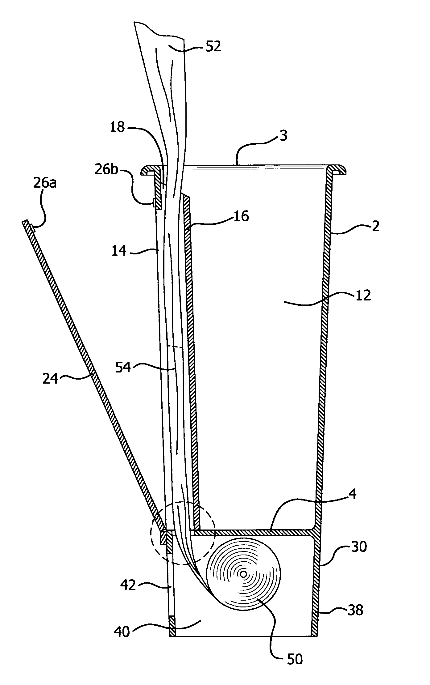
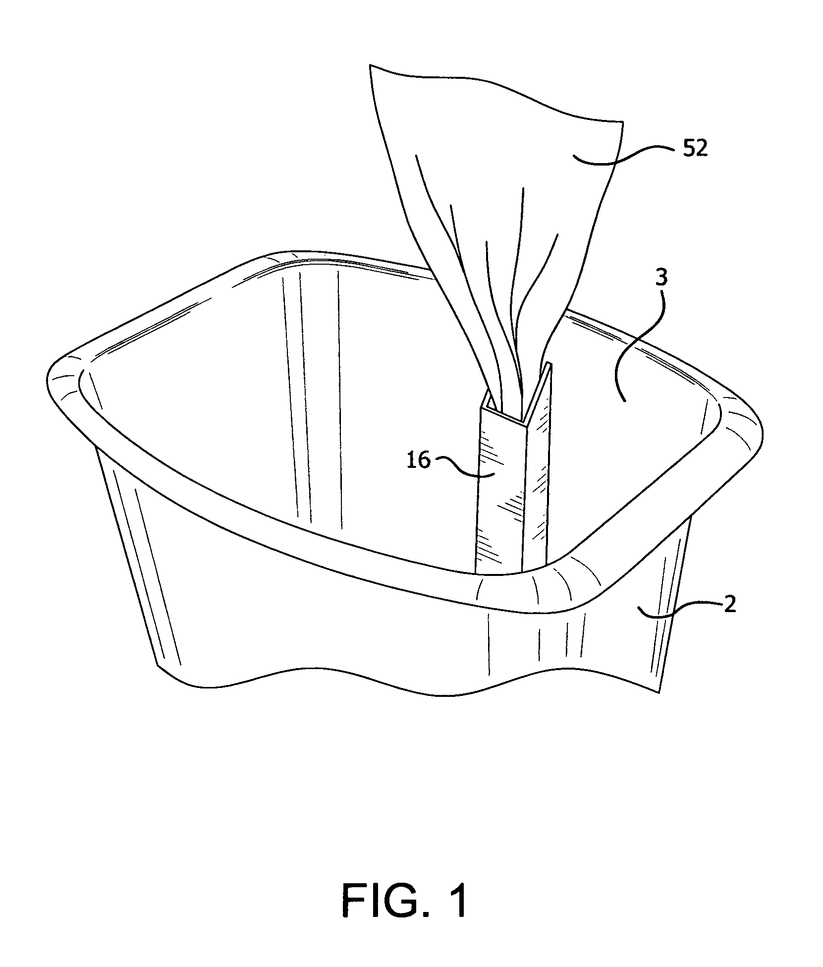
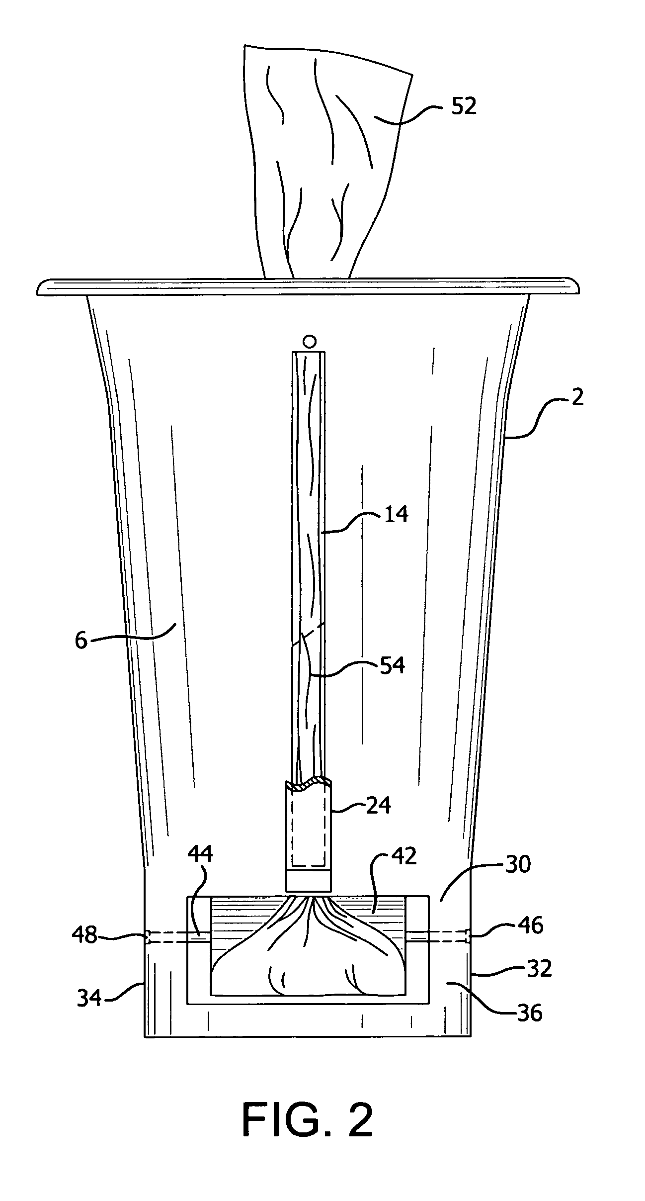
[0014]The trash receptacle with trash bag dispenser system of the present invention comprises container 2 having bottom floor 4 and front wall 6 with internal surface 8 and external surface 10. See FIG. 4. Container 2 has open top 3 for receiving trash to be collected within interior space 12 of the container. Slotted through opening 14 extends from bottom floor 4 upwards along substantially the entire length of front wall 6 of container 2.

[0015]Channel member 16, extending inward into interior space 12 of container 2, encloses slotted through opening 14 within the interior space. Channel member 16 has open top 18 and open bottom 20. Top 18 can be partially covered by an optional closure member having an opening with serrated edges. Open bottom 20 is aligned with opening 22 through bottom floor 4. Cover 24, pivotably mounted onto exterior surface 10 of front wall 6, is configured to cover slotted opening 14 and be secured in place by Velcro®26a / 26b or equivalent attachments. See FIG...


PUM


Abstract

A trash bag receptacle with trash bag dispenser system has an open top, a bottom floor, and a front wall. The front wall of the container has a slotted opening which extends from the bottom floor upwards along substantially the entire length of the front wall. A channel member with an open top and bottom extends inward into the container, enclosing the slotted opening within the container. A base section supporting the container has an interior space in which a roll of trash bags is rotatably mounted. A single trash bag from the roll is threaded from the interior space and through the channel. The trash bag exits from the open top of the channel where its perforation is separated from the roll of trash bags. The adjacent, next trash bag on the roll remains in the channel member. A new, clean trash bag is thus easily accessible to the user by simply pulling the next trash bag which is exposed through the open top of the channel member.

Description

BACKGROUND OF THE INVENTION[0001]Home or office trash receptacles or containers are commonly utilized in combination with disposable trash bags which are inserted into the containers as liners. When the trash bag in a container is filled, it is removed and replaced with a clean, empty bag. However, boxes or rolls of clean bags are usually stored in different locations or even different rooms than the trash container itself. This requires the user to search for and locate the replacement bags and return a single bag to the trash container. In addition, it is common to store extra trash bags in the bottom of the container, under the bag which is being filled with trash. In this case, the user must reach into a usually dirty container and pull out a single bag. This is not only unsanitary, but is also sometimes difficult, since most bags today come in a roll or compact package and they are connected by perforations. As a result, a single bag must be manually ripped from the roller or p...

Claims


Application Information

Patent Timeline
Patent Type & Authority Patents(United States)
IPC IPC(8): B65D25/14B65D35/14B65D90/00
CPCB65F1/062
Inventor ZAWROTNY, LEANNEFRIES, DOREEN
Owner ZAWROTNY LEANNE
Learn More