Image display apparatus and image display method

a technology of image display and image, which is applied in the direction of printers, cameras, instruments, etc., can solve the problems of inability to accurately adjust the focus of scanning light, inability to achieve image formation on the retina, and extremely small amount of reflected light from the retina

Inactive Publication Date: 2012-11-27
PANASONIC CORP
View PDF7 Cites 3 Cited by
  • Summary
  • Abstract
  • Description
  • Claims
  • Application Information

AI Technical Summary

Benefits of technology

[0010]Therefore, an object of the present invention is to provide an HMD-type image display apparatus and an image display method, for solving the above problems, by which focus adjustment of scanning light can be performed accurately, thereby constantly maintaining a desired image formation state on a retina.
[0015]Further, preferably, the control section detects the view line direction of the user by detecting a peak of an amount of the reflected light detected by the light detection section, and controls the focus position adjustment section to increase adjustment accuracy of the focus position during projecting of an image in a region of the detected view line direction, and to decrease the adjustment accuracy of the focus position during projecting of an image in another region.
[0024]As described above, the image display apparatus and the image display method of the present invention perform focus adjustment of laser light, which is used for scanning, by using reflected light from a cornea whose amount is relatively large. Thus, the image display apparatus and the image display method of the present invention can accurately perform focus adjustment of the scanning light for the entire visual field of the user, thereby constantly maintaining a desired image formation state on the retina.

Problems solved by technology

Here, there are individual differences in human eyes (eyesight, curved shape of retina, etc.), and failure of image formation on the retina may occur due to the individual differences.
Further, although not being a technology for eliminating the above failure of image formation to obtain a desired image formation state, for example, there is a technology disclosed in Japanese Patent Laid-Open Publication No.
Further, when the scanning light is incident on the retina from the direction inclined at an angle with respect to the view line direction of the viewer, namely, when specularly reflected light from the retina is not obtained, the amount of the reflected light from the retina is extremely small.
Thus, in the conventional technology, detection error of the reflected light from the retina is large, and hence, the focus adjustment of the scanning light may not be performed accurately and an image formation state on the retina may not be adjusted accurately.
Further, particularly, in the peripheral visual field of the user in which specularly reflected light is not obtained from the retina, an image formation state on the retina may be not adjusted.

Method used


Image

  • Image display apparatus and image display method
  • Image display apparatus and image display method
  • Image display apparatus and image display method

Examples


first embodiment

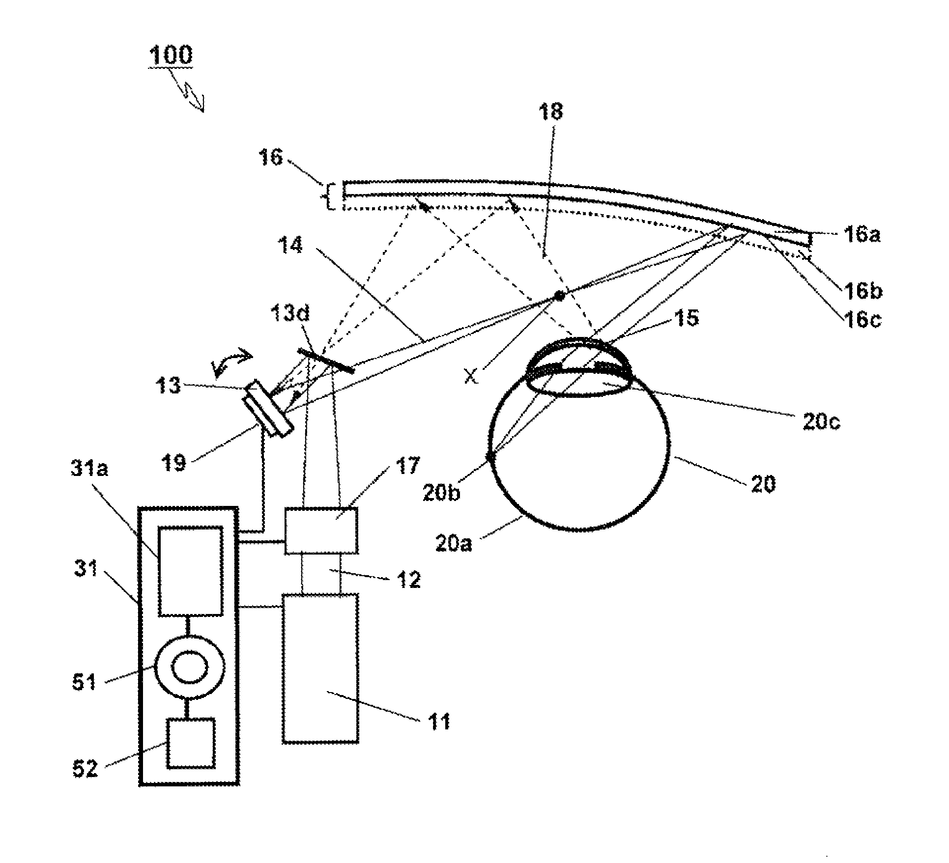
[0032]FIG. 1 shows an example of a schematic configuration of an image display apparatus 100 according to a first embodiment. First, the image display apparatus 100 will be described briefly with reference to FIG. 1. As shown in FIG. 1, the image display apparatus 100 includes a laser light source 11, a focus position adjustment section 17, a reflection mirror 13d, a scanning section 13, a light deflection section 16, a light detection section 19, and a control part 31. The control part 31 includes a control section 31a, an adjustment section 51, and a storage section 52. In FIG. 1, an eye 20 of a viewer (hereinafter, referred to as a user) whose eye is scanned is shown.

[0033]The laser light source 11 emits laser light 12 for projecting an image on the retina 20a of the eye 20, and changes the intensity and the color of the laser light 12 in accordance with control of the control part 31.

[0034]The focus position adjustment section 17 adjusts the focus position of the laser light 12 ...

second embodiment

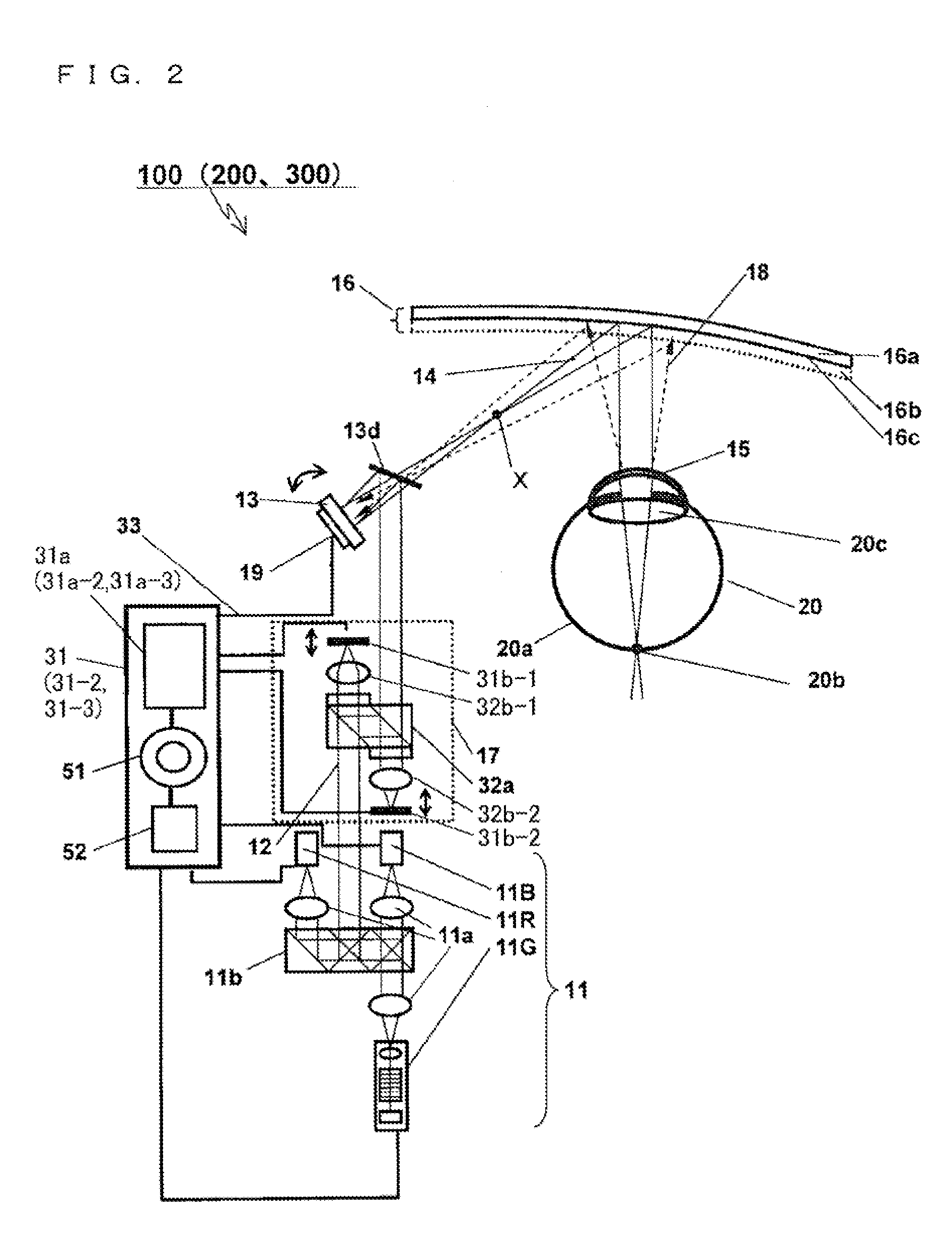
[0078]In addition to the features of the image display apparatus 100 according to the first embodiment, an image display apparatus 200 according to a second embodiment has a feature of detecting the view line direction of a user, providing a clear image in a region (a central visual region of the user) corresponding to the detected view line direction, and providing a relatively unclear image in the other regions (a peripheral visual region of the user).

[0079]The image display apparatus 200 according to the second embodiment has a configuration in which the control part 31 of the image display apparatus 100 according to the first embodiment is replaced with a control part 31-2. The control part 31-2 of the image display apparatus 200 has a configuration in which the control section 31a of the control part 31 of the image display apparatus 100 is replaced with a control section 31a-2. Thus, the following will describe the difference from the image display apparatus 100 according to t...

third embodiment

[0084]In addition to the features of the image display apparatus 100 according to the first embodiment, an image display apparatus 300 according to a third embodiment has a feature of detecting the view line direction of a user, and changing an initial setting signal, used for focus adjustment, so as to follow a change of the view line direction.

[0085]The image display apparatus 300 according to the third embodiment has a configuration in which the control part 31 of the image display apparatus 100 according to the first embodiment is replaced with a control part 31-3. The control part 31-3 of the image display apparatus 300 has a configuration in which the control section 31a of the control part 31 of the image display apparatus 100 is replaced with a control section 31a-3. Thus, the following will describe the difference from the image display apparatus 100 according to the first embodiment with reference to FIG. 2. For the same content as that of the image display apparatus 100 a...


PUM


Abstract

An image display apparatus and method constantly maintain a desired image formation state on a retina. The apparatus includes a laser light source for emitting laser light, a focus position adjustment section for adjusting a focus position of the laser light, and a scanning section for scanning an area by using the adjusted laser light as scanning light. The apparatus also includes a light deflection section for leading the scanning light to a user's cornea, a light detection section having an optically conjugate relation with the cornea surface through the light deflection section, for detecting a part the scanning light reflected on the cornea surface and generating a detection signal, and a control section. The control section controls the focus position adjustment section to adjust the focus position of the laser light such that the detection signal agrees with an initial setting signal.

Description

BACKGROUND OF THE INVENTION[0001]1. Field of the Invention[0002]The present invention relates to a head-mounted display and the like, and more particularly, to an image display apparatus and an image display method by which a person can view a clear image with the naked eye.[0003]2. Description of the Background Art[0004]An image display apparatus as typified by a head-mounted display (hereinafter, referred to as an HMD) is a mobile display terminal for personal use, and has an eyeglass-shaped structure for easy wearing.[0005]Here, there are individual differences in human eyes (eyesight, curved shape of retina, etc.), and failure of image formation on the retina may occur due to the individual differences.[0006]As a technology for eliminating the above failure of image formation to obtain a desired image formation state, for example, there is a technology disclosed in Japanese Patent Laid-Open Publication No. H07-128613. In the technology in Japanese Patent Laid-Open Publication No...

Claims


Application Information

Patent Timeline
Patent Type & Authority Patents(United States)
IPC IPC(8): G03B21/00
CPCG02B27/0093G02B27/0172G02B27/40
Inventor ITOH, TATSUOKASAZUMI, KENICHI
Owner PANASONIC CORP
Why Eureka
Try Eureka