
Systems and methods for recognizing a target from a moving platform

a technology of moving platforms and target recognition, applied in the field of navigation systems, can solve the problems of insufficient data extraction from multiple databases of current navigation data sources to accurately position aircraft or other vehicles in relation to targets, too large a measurement for many purposes, and the low precision of the guidance system may become hampered

Active Publication Date: 2012-11-27
HONEYWELL INT INC
View PDF43 Cites 95 Cited by
  • Summary
  • Abstract
  • Description
  • Claims
  • Application Information

AI Technical Summary

Benefits of technology

The invention provides systems and methods for recognizing the location of a target by analyzing its edges. The system includes a camera, memory, and processor. The processor receives the camera data and the template data, and determines if the object is the target if it matches the template within a certain percentage error. This technology can be used in various applications such as in retail stores to recognize the location of a target product.

Problems solved by technology

The navigation data extracted from multiple databases of current navigation data sources is not sufficient to accurately position an aircraft or other vehicle (e.g., motor vehicles, military vehicles, etc.) in relation to a target.
Specifically, the resolution available using such navigation data sources is generally measured in meters, which may be too large a measurement for many purposes.
That is, a low precision guidance system may become hampered by severe weather conditions, which may present a potential challenge for safely landing an aircraft, navigating motor vehicles along a terrestrial route, and / or tracking targets of interest.
When there are significant changes in the scene or the target is moving rapidly, this type of analysis usually results in jitter due to incomplete motion compensation from the sensor and / or the platform.

Method used


Image

  • Systems and methods for recognizing a target from a moving platform
  • Systems and methods for recognizing a target from a moving platform
  • Systems and methods for recognizing a target from a moving platform

Examples


Embodiment Construction

[0017]The following detailed description is merely exemplary in nature and is not intended to limit the invention or the application and uses of the invention. Furthermore, there is no intention to be bound by any theory presented in the preceding background or the following detailed description.

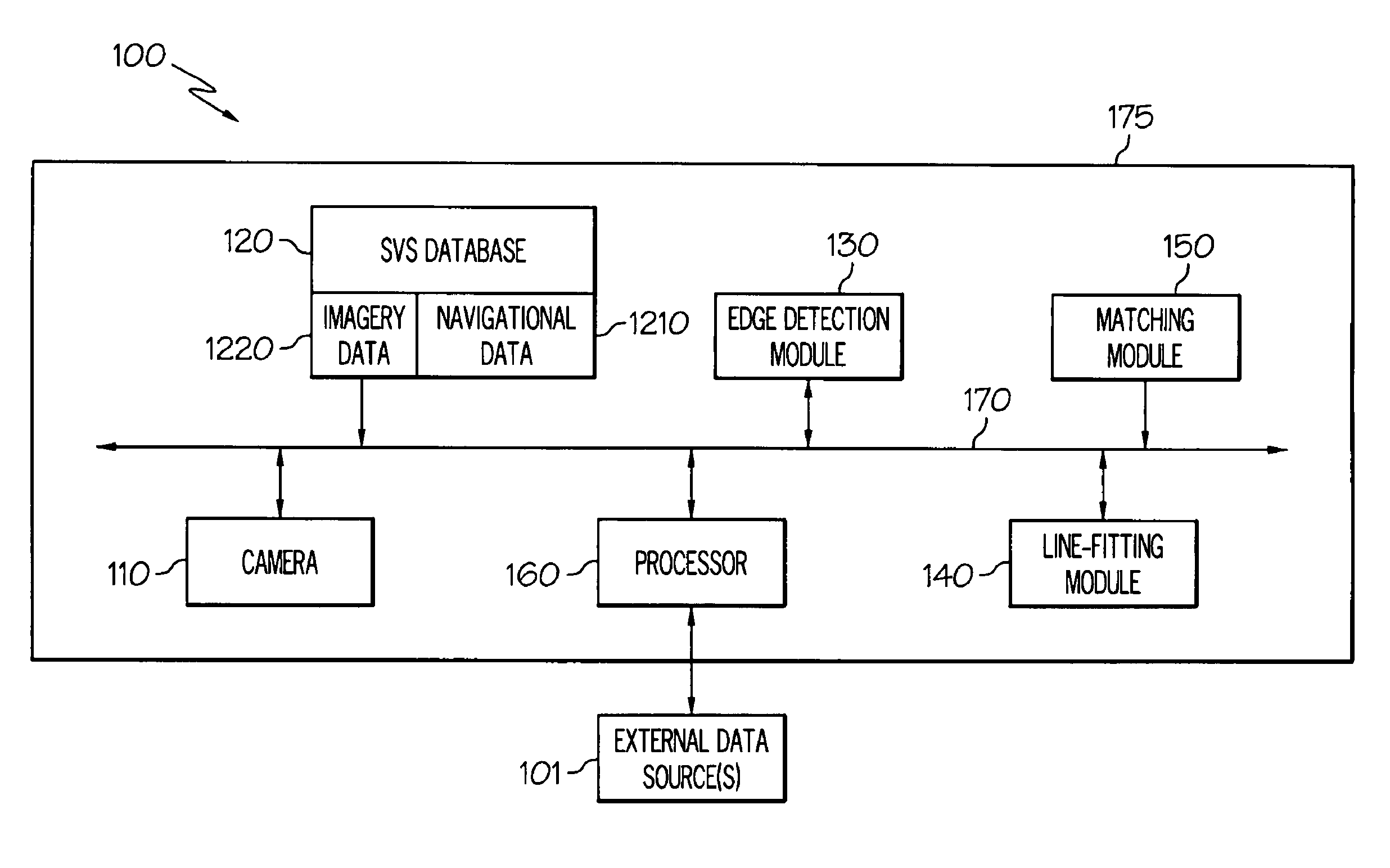
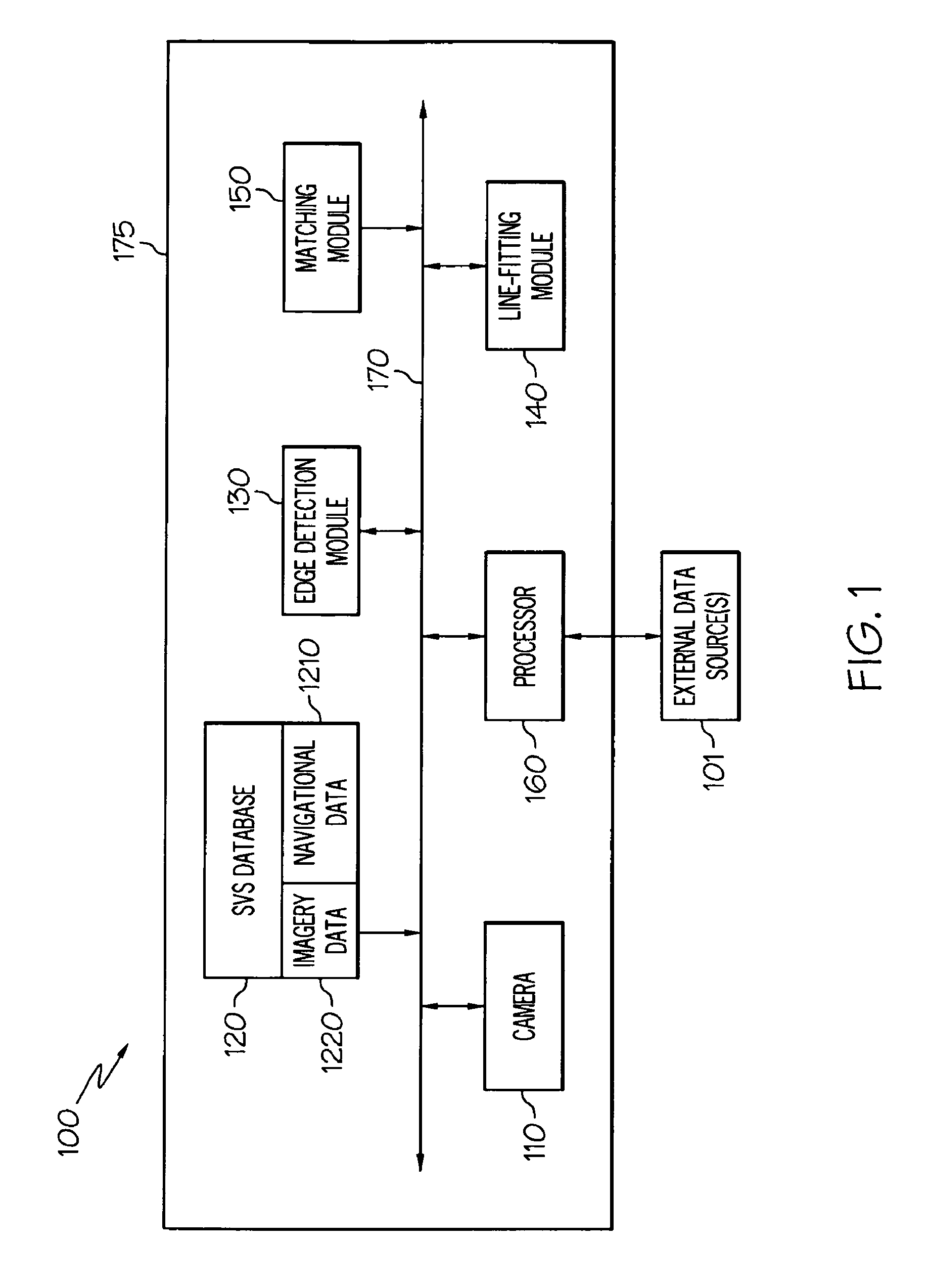
[0018]FIG. 1 is a block diagram of an exemplary system 100 for recognizing the location of a target. In the illustrated embodiment, system 100 comprises a camera 110, a synthetic vision system (SVS) database 120, an edge detection module 130, a line fitting module 140, a matching module 150, and a processor 160 coupled to one another via a bus 170. Processor 160 is also coupled to one or more external sources of data 101 (e.g., map databases, global positioning systems, navigation systems, etc.) related to various geographical regions.

[0019]Camera 110 may be an infrared (FLIR) camera or other type of camera configured to detect and capture one or more digital images of an environment surroun...


PUM


Abstract

Systems and methods for recognizing a location of a target are provided. One system includes a camera configured to generate first data representing an object resembling the target, a memory storing second data representing a template of the target, and a processor. The processor is configured to receive the first data and the second data, and determine that the object is the target if the object matches the template within a predetermined percentage error. A method includes receiving first data representing an object resembling the target, receiving second data representing a template of the target, and determining that the object is the target if the object matches the template within a predetermined percentage error. Also provided are computer-readable mediums including processor instructions for executing the above method.

Description

CROSS-REFERENCE TO RELATED APPLICATIONS[0001]This application claims the benefit of U.S. Provisional Application No. 61 / 031,905, filed on Feb. 27, 2008.TECHNICAL FIELD[0002]The present invention generally relates to navigations systems, and more particularly relates to systems and methods for recognizing a target while a platform is in motion.BACKGROUND[0003]The need to detect and track targets (e.g., runways, landing strips, landing pads, roads, obstacles, objects, landmarks, and the like) from moving platforms is driving the development of sensor fusion and computer vision algorithms for next-generation situational awareness and navigation systems. For example, landing an aircraft, whether an unmanned air vehicle (UAV) or manned vehicle, requires accurate information about the location of the runway. Similarly, military targeting systems for urban environments require accurate localization to decrease or avoid altogether collateral damage and civilian casualties.[0004]The navigati...

Claims


Application Information

Patent Timeline
Patent Type & Authority Patents(United States)
IPC IPC(8): G06K9/62
CPCG06T7/0044G06K9/00798G06T7/0085G06T7/74G06T7/13G06V20/588
Inventor HAMZA, RIDA M.MOHIDEEN, MOHAMMED IBRAHIM
Owner HONEYWELL INT INC
Learn More