Coin Identification Method and Apparatus

a coin identification and apparatus technology, applied in coin testing, instruments, computing, etc., can solve the problems of low effort directed towards the automatic identification of coinage features deliberately minted, difficult and time-consuming identification and retrieval of specific date and mint difficulty in identifying and retrieving coins from general circulation, etc., to achieve high degree of automation, high tolerance, and convenient use

Inactive Publication Date: 2012-11-29
IDENTICOIN
View PDF9 Cites 83 Cited by
  • Summary
  • Abstract
  • Description
  • Claims
  • Application Information

AI Technical Summary

Benefits of technology

[0013]In one embodiment, the method and apparatus described herein is implemented in conjunction with publicly used coin counting kiosks. Such coin counting devices are typically used for processing and/or discriminating coins or other objects, such as discriminating among a plurality of coins or other objects received all at once, in a mass or pile, from the user, with the coins or objects being of many diffe

Problems solved by technology

Optical sensor methods have been primarily directed towards the discrimination among coins of similar electromagnetic and physical properties, yet not authentic with respect to a specific sovereignty, such as coins originating from a foreign country or entity.
However, little effort has been directed towards the automated identification of coinage features deliberately minted, yet not universally present on coins of the same denomination or type, such as details indicating the date and the location of mint of a coin.
Currently, identifying and retrieving coins of specific date and mint from general circulation is difficult and time consuming.
Date and mint information is typically determined “by eye,” sometimes with the aid of magnification, and can often be taxing on the individual as the examination of a large number of coins can be tedious and time consuming.
There is currently no device which automates the identification of these coin attributes, nor one which can do so at h

Method used


Image

  • Coin Identification Method and Apparatus
  • Coin Identification Method and Apparatus
  • Coin Identification Method and Apparatus

Examples


Embodiment Construction

[0046]The detailed description set forth below in connection with the appended drawings is intended as a description of presently-preferred embodiments of the invention and is not intended to represent the only forms in which the present invention may be constructed or utilized. The description sets forth the functions and the sequence of steps for constructing and operating the invention in connection with the illustrated embodiments. However, it is to be understood that the same or equivalent functions and sequences may be accomplished by different embodiments that are also intended to be encompassed within the spirit and scope of the invention.

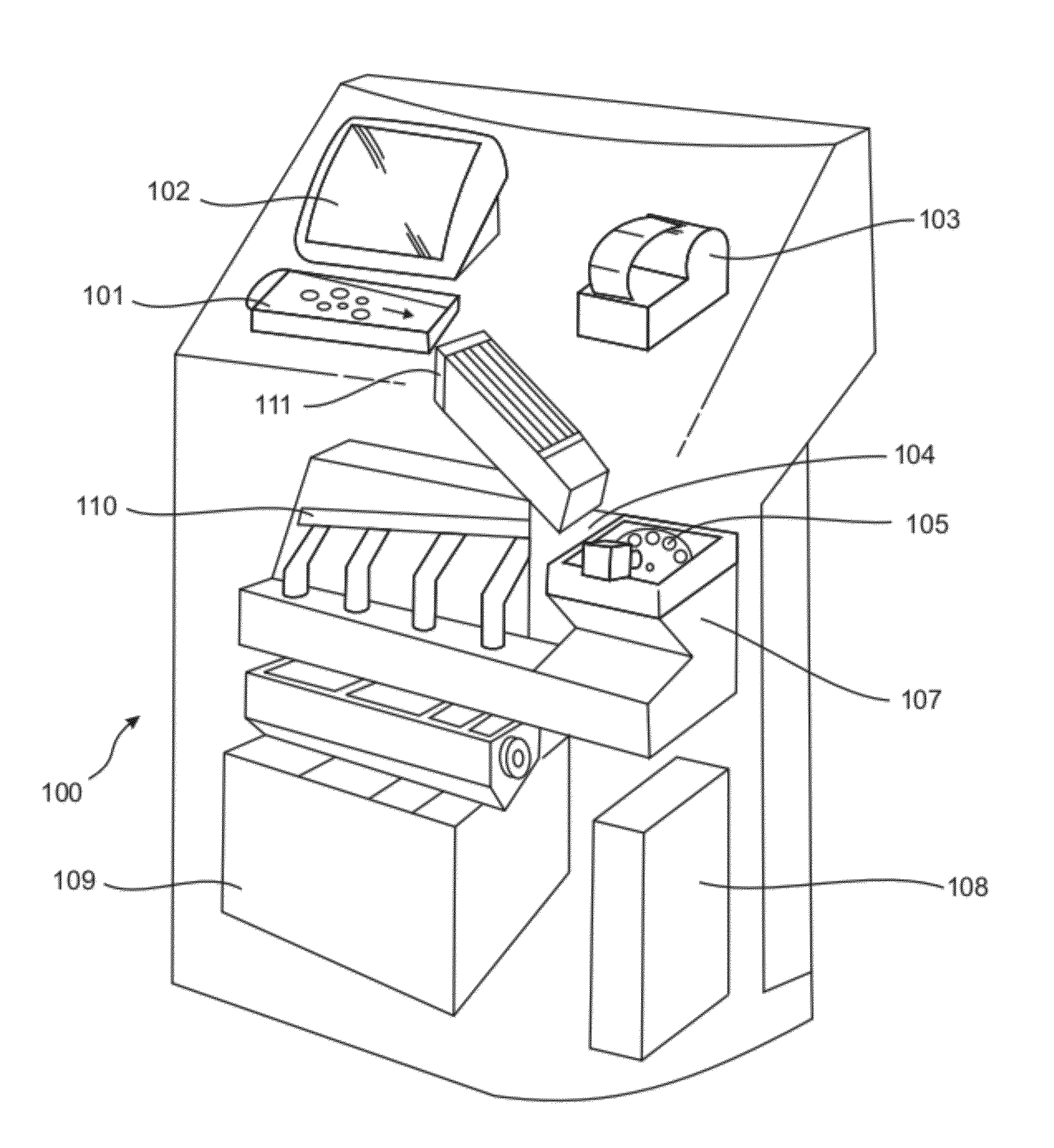
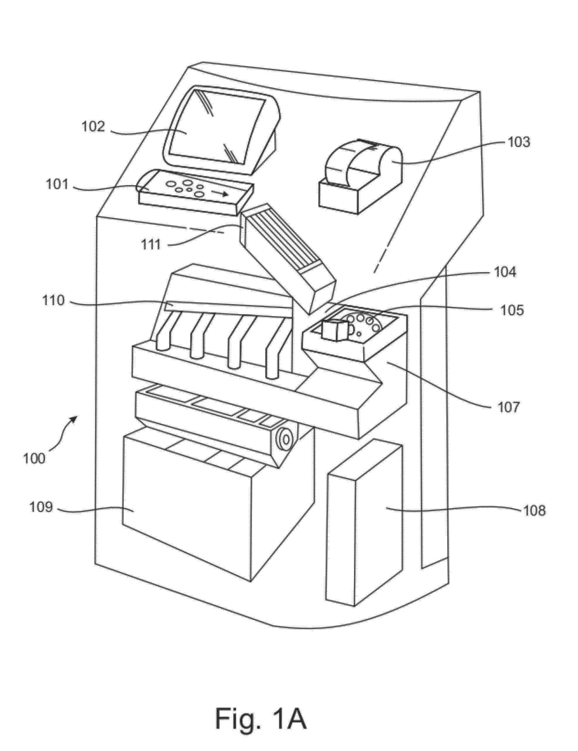
[0047]The coin identification method and apparatus described herein can be used in connection with, or as an enhancement to, a number of devices and purposes. One such implementation is illustrated in FIG. 1A. In this device 100, coins are placed into a tray 101, and fed to an imaging region or area 105 via a first ramp 111 and coin pickup ...


PUM


Abstract

A coin identification method and apparatus capable of reliably acquiring stable two-dimensional images of both surfaces of coins 217, and using the acquired two-dimensional images to perform identification and discrimination, reliably and at high speed, between coin denomination, types, dates and origins of mint. In a coin pathway, imaging devices 207a,b are positioned at an image-capture position such that images above and below the surface of passing coins are captured under illumination. The coin denomination is identified by geometric measurements of enhanced images, the coin type is identified by matching templates to enhanced images, and the coin date and mint are identified using template matching to segmented sub-images. In one embodiment, the coin identification information is used for the promotion of a coin counting service. The results are displayed in an entertaining and engaging manner.

Description

TECHNICAL FIELD OF INVENTION[0001]The present invention relates to an apparatus and method for identifying coins, more specifically identifying the denomination, type, date, and mint of coins which may be used for the discrimination of coins by said attributes and the promotion of a coin counter.BACKGROUND OF THE INVENTION[0002]Coin identification methods are often used for the purposes of determining the denomination and authenticity of coins and often for the purposes of mechanically discriminating coins based on that information. The most common coin discrimination devices, such as those used in automatic vending machines, coin-to-currency changers, gaming devices such as slot machines, bus or subway token “fare boxes”, and the like, generally employ inductive coin testing methods to determine the denomination and authenticity of coins. These methods typically work by measuring the effect of a coin on an alternating electromagnetic field produced by one or more coils disposed at ...

Claims


Application Information

Patent Timeline
IPC IPC(8): G06K9/62
CPCG07D5/005G07D3/14
Inventor DABIC, STEVEN
Owner IDENTICOIN
Why Eureka
Try Eureka